Chapter 7 : Concrete mix design
Introduction:
Portland cement concrete is a composite material in which
the cement and water forms a paste or glue, which bends the coarse and fine
aggregates. The quality of the formed concrete depends on the properties of the
ingredients and how well they fit together.
When mix designing concrete one should talk in
consideration finding the optimum well-designed and proportioned mixture that
also should be sufficiently workable to enable transport, handling, placing and
finishing. Ideally, the mixture should be economical will satisfy the terms of
properties of the final hardened concrete and will make effective use of
locally available materials.
Mix Design is the process of determining required
characteristics of the concrete mixture. That includes permissible or desirable
aggregate size, workability, required strength or other mechanical properties,
durability requirements, governing water-cementitious materials ratio and the
determination of permitted or excluded ingredients. Then the mixture is
proportioned, determining the appropriate quantities of all the ingredients
making adjustments to compensate for local materials while achieving the
specified characteristics of the concrete. The mix proportions are similar to
the "shop drawings" in the design of steel while the mix design
develops the concrete specifications.
Strength is the most important performance requirement and
measured at 28 days, the yield strength should exceed the specified value by
and amount that is unique to each concrete producer depending on the Q/C
measures which reflects of the standard deviation of the 28 days strength test
results in the batch plant.
The compressive strength that the concrete should be
designed for should take in consideration a safety factor that covers the fact
that 28-days compressive strength may vary in the same mix due to changes in
materials, changes in mixing and weighing or the way it is handled at the site.
After strength, workability expressed as "slump" is the most common specification requirement. Normally imposed as a maximum value. But the slump-workability relation is not solid and only makes sense some of the time. It varies from being clearly established to non-existing.
Constant slump can be
achieved batch after batch only when all of the input materials remains the
same, mixing time and speeds too also when the slump is measured at the same
time relative to the batching.
When resistance to the
effect of the freezing and thawing of the absorbed water is required, the
hardened concrete needs a system of internal air voids with an appropriate
total volume, distribution of sizes and spaces between voids.
The freezing and thawing
resistance can be specified by simply requiring a specific total air content in
the fresh concrete. so that when the concrete hardens, it will contain millions
of microscopic air cells which will relieve the internal pressure on the
concrete by providing tiny chambers for the expansion of the water when it
freezes. All mixed fresh concrete got air entrained but if the air content is
lower than the specs required for freeze resistance, the use of air entrained admixtures
is required.
We can control the porosity
and permeability of the cement paste by limiting the w/c ratio of the paste
that means the less w/c the less paste there is, the thicker the past or glue
is the less voids content left from hydration the less the permeability.
Achieving durability is much harder than other mechanical requirements on the
long run.
If the determined amount of
air content is not sufficient the decision of using air entraining admixtures
should be taken with respect to the conditions the concrete we are designing
will be exposed to.
But the increase of the air
content will decrease the strength of the concrete and increase the
workability. At the same time the decrease in the w/c ratio to decrease
porosity will increase the strength.. the design must balance all these factors
to produce durable thus still workable concrete.
The quality of the cement
paste is described by the w/c ratio. the higher the w/c the more dilute the
glue holding the aggregate. The lower the w/c the more concentrated the glue, which also means the greater
it's strength because of the low porosity and higher density.
Although using a low w/c will enhance the mechanical properties such as the compressive strength, tensile strength, modulus of elasticity and the durability of the hardened concrete. It will also decrease the concrete workability that must be taken into consideration when mix designing the concrete.
Specific gravity (SG) is
the weight of a material divided
by the weight of an equal volume of water. That is if a material has a SG of
2.5 , that means that it will be 2 1/2 times heavier than water.
SG water = 1.0
SG cement = 3.15
Each material consists of
solids and pores. and these pores could contain water and the materials weight will vary depending on the amount of
water in the pores. That is why the SG is always measured at a fixed moisture
content.
Absolute volume : specific
gravity of an aggregate doesn't measure the quality of that aggregate but is a
helpful tool in determining the absolute volume that a given weight of an
aggregate will occupy in the mix the term Absolute Volume refers to the space
occupied by the aggregates
particles including the internal pores but not including the voids between
those particles.
Absolute Volume = weight /
absolute unit weight
Absolute unit weight= SG
(dry)* unit weight of water (1000 Kg/m3)
if the SG of aggregates changes for the same batch that means a decrease or increase in the yield or volume of concrete and if batch proportion remain constant will result in too much or too little concrete. Meaning changes in volume and weigh of the m³.
Unit weight : the weight per unit volume of the compacted agg. a high unit weight means better grading and better packing and also means that more quantities can be used without effecting the workability.
Concrete mix design
ACI Absolute volume Method
|
Step (1) |
Set design requirements |
The following information must be provided:
-
Required
compressive strength at 28 days.
-
Required
slump.
-
Exposure
conditions.
-
Maximum
size of coarse aggregates to be used.
|
Step (2) |
Test the aggregate |
The following lab results should be obtained:
-
Specific
gravity of coarse and fine aggregates.
-
Absorption
of coarse and fine aggregates.
-
Moisture
content of coarse and fine aggregates.
-
Rodded
oven dry unit weight of coarse aggregate.
-
Fineness
modulus of the fine aggregate.
-
Grading
of the available fine and coarse aggregates.
|
Step (3) |
The recommended slump |
If the required slump is not specified, use the following
table:
|
Recommended
slumps for various types of construction |
||
|
Type of
construction |
Max. Slump (mm) |
Min Slump (mm) |
|
Reinforced foundation walls and footings |
75 |
25 |
|
Plain footings caissons and substructure |
75 |
25 |
|
Beams and reinforced walls |
100 |
25 |
|
Building columns |
100 |
25 |
|
Pavements and slabs |
75 |
25 |
|
Mass concrete |
75 |
25 |
|
Step (4) |
The design
compressive strength |
The design compressive strength
= specified compressive strength + S.D*k
= f ’c = f c + S.D*k
Determining the design compressive strength:
1 Compute the standard deviation from the patch plant records of the compressive strength at 28 days. At least 30 test result must be available.
The slandered deviation for any concrete producer is:
_
S.D=
√ ∑ (Xn-Xavg)²
N-1
Where :
Xavg = (∑Xn)/n
Xn is a single result
∑X is the sum of the results
N is the number of the results
if the available test results are less than 30 but not less than 15 , the computed standard deviation should be modified:
S.Dnew=S.D*K
|
Number of test |
K |
|
15 |
1.16 |
|
20 |
1.08 |
|
25 |
1.03 |
|
30 or more |
1 |
If test results are less than 15 then use the following table to determine the standard deviation
f c
Specified strength |
f 'c Design strength |
|
Less than 21 N/mm2 |
F c + 7 |
|
21 - 35 N/mm2 |
F c +8.5 |
|
35 N/mm2 or more |
F c +10 |
As the data becomes available during construction the standard deviation is recalculated using the formulas.
2 Compute the design compressive strength
(f’c)
The design compressive strength is the larger of the two following equations:
F 'c = f c + (2.33 * SD) -3.5
F 'c = f c + 1.34*SD
|
Step (5) |
The mixing water |
Use the next table to
determine the amount of water needed to achieve the required slump:
Non-air entrained concrete
|
||||
Approximate mixing water (Kg/m3)
for indicated nominal size
of aggregate
|
||||
|
Max. size (mm) |
Slump (mm) |
|||
|
25-50 |
75-100 |
150-175 |
>175 |
|
|
9.5 |
207 |
228 |
243 |
N/A |
|
12.5 |
199 |
216 |
228 |
N/A |
|
19 |
190 |
205 |
216 |
N/A |
|
25 |
179 |
193 |
202 |
N/A |
|
37.5 |
166 |
181 |
190 |
N/A |
|
50 |
154 |
169 |
178 |
N/A |
|
75 |
130 |
145 |
160 |
N/A |
|
150 |
113 |
124 |
N/A |
N/A |
Air entrained concrete
|
||||
Approximate mixing water (Kg/m3) for indicated nominal size of aggregate
|
||||
|
Max. size (mm) |
Slump (mm) |
|||
|
25-50 |
75-100 |
150-175 |
>175 |
|
|
9.5 |
181 |
202 |
216 |
N/A |
|
12.5 |
175 |
193 |
205 |
N/A |
|
19 |
168 |
184 |
197 |
N/A |
|
25 |
160 |
175 |
184 |
N/A |
|
37.5 |
150 |
165 |
174 |
N/A |
|
50 |
142 |
157 |
166 |
N/A |
|
75 |
122 |
133 |
154 |
N/A |
|
150 |
107 |
119 |
N/A |
N/A |
|
Step (6) |
The Air content |
Determine the percent of
entrapped air in the paste with respect to the maximum size of aggregates used.
|
Approximate amount of air in non air-entrained
concrete (%) |
|
|
Nominal max. size |
% air |
|
9.5 |
3 |
|
12.5 |
2.5 |
|
19 |
2 |
|
25 |
1.5 |
|
37.5 |
1 |
|
50 |
0.5 |
|
75 |
0.3 |
|
150 |
0.2 |
|
Step (6) |
Dosage
of Air-entraining agent |
If the actual air content is
not sufficient the decision of using air-entraining admixtures should be taken
with respect to the conditions the concrete we are designing will be exposed
to.
|
Approximate
amount of air in air-entrained concrete (%) |
|||
|
Nominal max. size |
% Air required |
||
|
|
Mild Exposure |
Moderate Exposure |
Severe Exposure |
|
9.5 |
4.5 |
6 |
7.5 |
|
12.5 |
4 |
5.5 |
7 |
|
19 |
3.5 |
5 |
6 |
|
25 |
3 |
4.5 |
6 |
|
37.5 |
2.5 |
4.5 |
5.5 |
|
50 |
2 |
4 |
5 |
|
75 |
1.5 |
3.5 |
4.5 |
|
150 |
1 |
3 |
4 |
Mild Exposure
Includes indoor or outdoor
service in a climate that does not expose the concrete to freezing or deicing
agents. When you want air entrainment for any reason other than durability,
such as to improve workability or cohesion or to improve strength in
low-cement-factor concrete, you can use air contents that are lower than those
required for durability.
Moderate exposure
means service in a climate
where freezing is expected, but where the concrete is not continually exposed
to moisture or free-standing water for long periods before freezing or to
deicing agents or other aggressive chemicals. Structures that do not contact
wet soil or receive direct applications of deicing salts are exterior beams,
columns, walls, girders, and slabs.
Severe exposure
Where the concrete is
exposed to deicing chemicals or other aggressive agents or where the concrete
continually contacts moisture or freestanding water before freezing. Examples
are pavements, bridge decks, curbs, gutters, sidewalks, canal linings, or
exterior water tanks or slumps.
contact wet soil or receive
direct applications of deicing salts are exterior beams, columns, walls,
girders, and slabs.
NOTE : If
the concrete is not continually wet and will not be exposed to deicing salts,
lower air content values such as the ones in the non-air entraining concrete
table could be used for moderate exposure though the concrete is exposed to
freezing and thawing.
|
Step (7) |
Determine the w/c ratio |
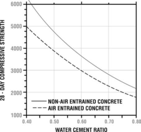
Use the following tables or the figure to determine the required w/c ratio for achieving the design compressive strength:
|
Relationship between w/c ratio and compressive
strength |
|
|
Compressive strength 28 days MPa (N/mm2) |
w/c ratio |
|
Non air entrained concrete |
|
|
40 |
0.42 |
|
35 |
0.47 |
|
30 |
0.54 |
|
25 |
0.61 |
|
20 |
0.69 |
|
15 |
0.79 |
|
Relationship between w/c ratio and compressive
strength |
|
|
Compressive strength |
w/c ratio |
|
28 days MPa (N/mm2) |
Air entrained concrete |
|
40 |
N/A |
|
35 |
0.39 |
|
30 |
0.45 |
|
25 |
0.52 |
|
20 |
0.6 |
|
15 |
0.7 |
The above w/c are determined form the results of 150*300 cylinders and are not suitable for the design of concrete tested in cubes, the mean strength should be corrected for the equivalent cylinder value first.
|
Step (8) |
Check w/c ratio |
Check the computed w/c ratio with the maximum permissible w/c ratio in sever exposure.
|
Maximum permissible w/c ratio for concrete in
severe exposure |
|||
|
|
Structure wet continuously or frequently and exposed to frequent freezing and thawing |
Structure exposed to sea water or sulfates |
|
|
Thin sections (railings, Curbs, sills, ledges, Ornamental work), and sections with less then 25 mm cover over steel |
0.45 |
0.4 |
|
|
All other structures |
0.5 |
0.45 |
|
|
Step (9) |
Compute the cement content |
Cement content = water content / w/c ratio
C =W / (w/c)
|
If Fly Ash (PFA) is used
: |
1 The Water content should be reduced:
Reduction in the free water content when PFA is used (kg/m³) |
||||
|
% PFA in
concrete |
Slump (mm) |
|||
|
0-10 |
10-30 |
30-60 |
60-100 |
|
|
10 |
5 |
5 |
5 |
10 |
|
20 |
10 |
10 |
10 |
15 |
|
30 |
15 |
15 |
20 |
20 |
|
40 |
20 |
20 |
25 |
25 |
|
50 |
25 |
25 |
30 |
30 |
2 The cement and PFA contents are calculated as follows:
cement content = C = (100-p)W (reduced) .
(100-0.7) [ w/ (c + 0.3 F) ]
and PDF = F = p*C /(100-p)
where p is the percent of PFA.
And [ w/ (c + 0.3 F) ] is the water/cement ratio from the tables.
Procedure:
- Determine the w/(c+0.3F) ratio as a normal w/c ratio from the table.
- Reduce the water content as in the above table.
- Calculate C using the equation where [ w/ (c + 0.3 F) ] is the normal water/cement ratio from the tables.
- Calculate F from the equation where C is the value just computed.
- Compute the true water/cement ratio as:
w/c = W reduced
(C + F)
- Check the computed w/c ratio to the maximum w/c for durability
|
Step (10) |
Compute the Coarse aggregates content |
Use the table to find the bulk
frication of the coarse aggregates (CA%) in the unit volume of concrete.
Compute the coarse aggregate
content (CA)
CA= CA% * (Oven-Dry rodded
unit weight)
In calculating the coarse aggregate weight, the percent of coarse aggregates from the table is multiplied by the OD rodded unit weight not the (SG*1000).
|
Bulk volume
friction of coarse aggregates in the unit weight of concrete |
||||
|
Nominal max. size of aggregates
(mm) |
2.4 |
2.6 |
2.8 |
3 |
|
9.5 |
0.5 |
0.48 |
0.46 |
0.44 |
|
12.5 |
0.59 |
0.57 |
0.55 |
0.53 |
|
19 |
0.66 |
0.64 |
0.62 |
0.6 |
|
25 |
0.71 |
0.69 |
0.67 |
0.65 |
|
37.5 |
0.75 |
0.73 |
0.71 |
0.69 |
|
50 |
0.78 |
0.76 |
0.74 |
0.72 |
|
75 |
0.82 |
0.8 |
0.78 |
0.76 |
|
150 |
0.87 |
0.85 |
0.83 |
0.81 |
|
Step (11) |
Compute the fine aggregates content |
Absolute Volume = weight /
absolute unit weight
weight= SG (dry)* unit weight of water (1000 Kg/m3)
The only concrete component not calculate from the tables is the fine aggregates weight and it can be calculated the following logic:
Unit volume of concrete is
equal to the absolute volume of coarse, fine, air volume, cement volume and
water volume.
1 m³ = V(C) +V(W)
+V(air) +V(CA) + V(FA)
V(FA)=1 - V(C) -
V(W) - V(air) - V(CA)
Where:
V water = weight/unit weight = weight / 1000
V cement = weight/unit
weight = weight / 3.15*1000
V air =
percent air/100 * 1m³
V coarse = weight/absolute unit weight
= (percent coarse * OD rodded unit weight)/SG*1000
And the fine aggregates
content is :
→ FA= V(FA) * SG OD(fine)
* 1000
|
Step (12) |
Adjusting the aggregates weights |
Adjust
for the moisture in Aggregates
W (new)=
W+CA*[ Abs(CA)-Moist(C) ]/100+FA*[ Abs(FA)Moist(FA) ]/100
CA (new)= CA + CA * Moist(CA)
/100
FA (new)= FA + FA * Moist(FA) /100
Where Abs : absorption of the each type of aggregates.
And moist : the moisture in each type of aggregates
|
Step (13) |
Proportioning the coarse aggregates |
This method is helpful in determining the percent of each coarse aggregates gradation to be used to in order to produce the optimum combined aggregate gradation.
what is needed is the sieve analysis of each coarse gradation and the specs of the combined coarse aggregate. in addition to the specific gravity of each gradation.
P sieve = aA + bB + cC+ dD+….
Where:
P is the percent of materials passing a given sieve for the blended aggregate A,B,C,D,…. That means the allowed percent passing for that sieve in the specifications.
A,B,C,… percent material passing a given sieve for each aggregate that means the percent passing on that sieve for each of the gradations.
a,b,c,… proportions (decimal fractions) of the aggregates gradations to be blended.
For example:
|
sieve |
% passing |
% passing |
% passing |
% passing |
% passing |
|
agg1 |
agg2 |
agg3 |
agg4 |
specs |
|
|
3/4" |
45 |
32 |
30 |
28 |
40 |
|
1/2" |
19 |
19 |
16 |
12 |
17 |
P 3/4 =40 = 45a+32b+30c+28d
P 1/2 =17= 19a+19b+16c+12d
if there's four gradations of aggregate that means four unknowns (a,b,c,d) find four equations as above and assume (a=1) and solve them as a percent of (a)
eq(1) → b=f(c,d)
b=b
→ c=f(d) eq(5)
eq(2) → b=f(c,d)
eq(3) → b=f(c,d)
b=b
→ c=f(d) eq(6)
eq(4) → b=f(c,d)
from eq(5) and eq(6) → c=c find d
the results will be a percent of (a) for example:
a : b : c : d = 1 : 0.5 : 0.28 : 0.29
Knowing that a+b+c+d=1 sum of percents always equals 1.0
b=0.5a
c=0.28a
d=0.29a
Solve for a then b,c,d will follow
After the percent of each pile has been determined mix a pile and measure the rodded unit weight to be used in the mix design.. And compute the specific gravity of the mixed blend using the following :
SG tot = 1 /
( P1/100SG1 +P2/100SG2 +….+ Pn/100SGn)
SGtot is to be used in the calculation of the absolute volume of coarse aggregate.
Another helpful approach is given by the BS
|
Total coarse aggregate |
5-10 mm 3/16 – 3/8 in. |
1-20 mm 3/8 – ¾ in. |
20-40 mm ¾ - 1 ½ in |
|
100% |
33% |
67% |
---- |
|
!00% |
18% |
27% |
55% |
|
Step (14) |
Trial Batch Mix |
The calculated mix proportions should be checked by making trial mixes which must be tested for workability, cohesiveness, finishing properties and air content. as well as yield and density (unit weight). If any of those properties, except the last two, is unsatisfactory, adjustments to the mix proportions are necessary.
after the mix design is finished, and all the ingredients contents are determined, reduce these contents to a size suitable for mixing in the mixing equipment available (usually 0.02-0.04 m3) this is done by multiplying each ingredient weight by the trial batch size (Vt)
follow the slandered mixing procedure and add the amount of water (Wt) sufficient to produce a suitable slump regardless of the amount of the mixing water determined earlier in the mix design.
when a suitable readable slump is achieved, determine the slump (St) and the unit weight of the trial mix (UWt)
Keep in mind that the water content was changed and the original water content is W new=Wt / Vt
note that the size of the batch trial is changed now from the one that was used to determine the reduced trail content as the water content is not the same.
Vt new = ( sum of the content) / Uwt
the weight of water in the above sum is Wt
After achieving a readable slump, if the slump is still different from the required slump then this means that the water content (now Wnew) needs to be changed. A rule of thump for doing this is:
For each 25mm required change
in slump (St), increase or decrease the water content (W t) by 6 kg/m3
Note : ( 6 kg of water for the unit cubic meter not the trial batch size )
Wnew=Wt + the estimated water increase/decrease
The cement content must be change to maintain the original w/c ratio required for the strength and durability.
Cement content (new)= Wnew / (w/c)
Because the water content changed, all the other ingredients must change except the coarse aggregate, as the CA% in the mix design is independent of the paste volume.
CA new = reduced CA trial batch content / Vt new
now, to complete the unit volume of 1 cubic meter
V sand=1- V(CA)-V(air)-V(C
new)-V(W new)
Another trial batch is made based on the new contents and the above steps is repeated till the desired slump is required.
another approach for
solving the troubles slump is changing the aggregates gradation, shape, and
max. size but the effects of these changed on other properties must be observed
carefully.
|
Problem |
Solution |
|
The required slump is not achieved (workability problems) |
change the water content by 6 kg for each 25 mm slump increase/decrease and re-compute all the mix contents based on the new unit weight and batch size. |
|
decrease the coarse aggregates max. size or/and the gradation or/and the shape and type of aggregate |
|
|
The required Air Content is not achieved (durability problems) |
The dose of the air entraining admixture should be adjusted to produce the specified air content the water content is then increased (decreased) by 3 Kg/m3 for each 1% decrease (increase) in air content so as to maintained the required slump because the increase of air content increases the slump |
|
The produced density (unit weight) by the mass method is not achieved. |
If the density was important and critical, mix proportions should be adjusted to change the air content. |
|
The compressive strength is not achieved |
Plot the compressive test result and the w/c ratio on the BS curve and find a new w/c ratio then start all over. |
The British Method
|
Step (1) |
Set design requirements |
|
Step (2) |
Test the aggregate |
|
Step (3) |
The recommended slump |
If the required slump is not specified, use the following
table:
|
Degree of workability |
Slump (mm) |
Use for which concrete is
suitable |
|
Very low |
0-25 |
Roads
vibrated by power-operated machines. at the more workable end of this group,
concrete may be compacted in certain cases with hand-operated machines. |
|
Low |
25-50 |
Roads
vibrated by hand-operated machines. At the more workable end of this group,
concrete maybe manually compacted in roads using aggregate of rounded or
irregular shape. Mass concrete foundations without vibration or lightly
reinforced sections with vibration. |
|
Medium |
25-100 |
At the
less workable end of this group, manually compacted flat slabs using crushed
aggregate. Normal reinforced concrete manually compacted and heavily
reinforced sections with vibration. |
|
high |
100-175 |
For
sections with congested reinforcement. Not normally suitable for vibration |
|
Step (4) |
The design compressive strength |
Determining the design
compressive strength:
1 Compute the standard deviation from the patch plant records of the compressive strength at 28 days if the standard deviation is not available use the following table:
|
Plant
Q/C |
SD |
|
Excellent |
3 N/mm2 |
|
Good |
5 N/mm2 |
|
Poor |
7 N/mm2 |
2 Determine the factor relating to the
allowed percentage of the results to fall below the specified strength (f c) from this table:
|
K |
Percent of results below strength level |
|
0 |
50 |
|
1 |
16 |
|
1.28 |
10 |
|
1.64 |
5 |
|
1.96 (2) |
2.5 |
|
2.33 |
1 |
|
2.58 |
0.5 |
|
Infinity |
0 |
The British standards allow up to 2.5 % of results to fall bellow (f c)
3 Compute the
design compressive strength (f’c)
The design compressive strength
= specified compressive strength +
S.D*k
= f ’c = f c + S.D*k
|
Step (4) |
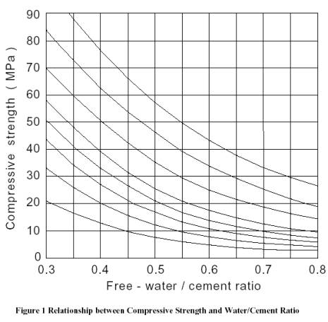
Determine the w/c ratio |
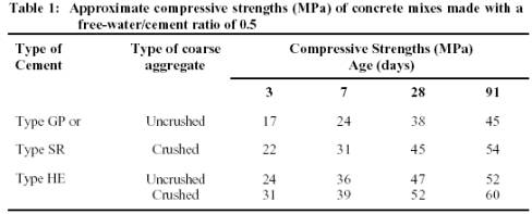
Use Table (1) to
determine the compressive strength of a concrete mix with w/c=0.5
Plot the w/c=0.5 and the
determined compressive strength on Figure (1) and draw a curve parallel
to the existing curves on the figure.
On the new curve inter the
value of the required design strength to find the suitable w/c ratio.
Check the w/c content with
the maximum allowable w/c for durability from Table (3). And use the
smallest value of w/c
|
Step (5) |
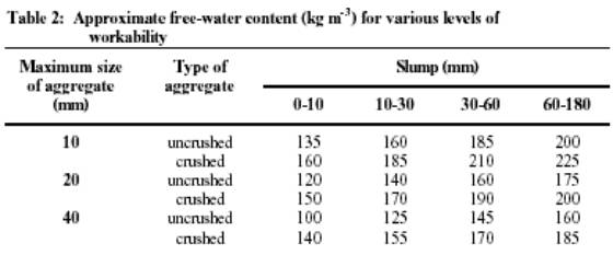
The water content |
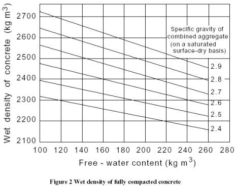
Find the free water content from Figure (2).
|
Step (6) |
The cement content |
Calculate the cement
content = C = W / (w/c)
Check the cement content
with the minimum cement content for durability from Table (2) and use
the larger value (compute a new W if needed)
|
Step (7) |
Determine the wet density |
Use Figure (3) to determine the estimated wet density of the concrete.
|
Step (8) |
Compute the total aggregate content |
Agg. total = Wet
density – ( C + W )
|
Step (9) |
Compute the fine aggregate content |
From Figure (3) determine
the percentage of the fine aggregates from the total aggregate content.
FA = %FA * Agg. total
|
Step (10 |
Compute the fine aggregate content |
Determine the coarse aggregate
content:
CA = Agg. total – FA
|
Step (12) |
Adjusting the aggregates weights |
Adjust
for the moisture in Aggregates
W (new)=
W+CA*[ Abs(CA)-Moist(C) ]/100+FA*[ Abs(FA)Moist(FA) ]/100
CA (new)= CA + CA * Moist(CA)
/100
FA (new)= FA + FA * Moist(FA) /100
Where Abs : absorption of the each type of aggregates.
And moist : the moisture in each type of aggregates
|
Step (13) |
Proportioning the coarse aggregates |
|
Step (14) |
Trial Batch Mix |

|
Environment |
Max. W/C |
Min. content of cementitious material Kg/m³ for nominal max of: |
Min. grade |
|||
|
40 mm |
20 mm |
14mm |
10 mm |
|||
|
Mild |
0.8 |
150 |
180 |
200 |
220 |
20 |
|
Moderate |
0.65 |
245 |
275 |
295 |
315 |
30 |
|
Severe |
0.6 |
270 |
300 |
320 |
340 |
35 |
|
Very Severe |
0.55 |
295 |
325 |
345 |
365 |
35 |
|
Extreme |
0.50 |
320 |
350 |
370 |
390 |
45 |
|
Table (3)-a for
plain concrete. Note: -The cementitious material doesn’t include any slag or PFA. -The minimum grade of 35 MPa for very severe conditions is applicable only to air-entrained concrete. |
||||||
|
Mild |
Concrete surface protected against weather or aggressive conditions. |
|||||
|
Moderate |
Concrete surface sheltered from sever rain or freezing whilst wet. Concrete subject to condensation. Concrete surface continuously under water. Concrete in contact with non-aggressive soil. |
|||||
|
Severe |
Concrete surface exposed too severe rain, alternating wetting and drying or occasional freezing or severe condensation. |
|||||
|
Very Severe |
Concrete surface exposed to seawater spray, de-icing salts (directly or indirectly), corrosive fumes or sever freezing conditions whilst wet. |
|||||
|
Extreme |
Concrete surface exposed to abrasive action like sea water carrying solids or flowing water with ph less or equal to 4.5 or machinery or vehicles |
|||||
|
Condition of exposure |
Nominal cover of concrete in mm |
||||
|
Mild |
25 |
20 |
20 |
20 |
20 |
|
Moderate |
- |
35 |
30 |
25 |
20 |
|
Severe |
- |
- |
40 |
30 |
25 |
|
Very severe |
- |
- |
50 |
40 |
30 |
|
Extreme |
|
|
|
60 |
50 |
|
|
|||||
|
Maximum w/c |
0.65 |
0.6 |
0.55 |
0.5 |
0.45 |
|
Minimum content of cementitious materials |
275 |
300 |
325 |
350 |
400 |
|
Minimum grade MPa |
30 |
35 |
40 |
45 |
50 |
|
Table (3)-b for reinforced and prestressed
concrete made with normal aggregates. |
|||||
|
Notes: -The above table applies when the maximum size of aggretes is 20mm when it’s 10mm and 14mm the content of cementitious materials should be increased by 40 kg/m³ and 20 kg/m³ for a maximum size of 40mm the content of cementitious materials can be reduced 30 kg/m³. -The cementitious materials not including any slag or PFA. |
|||||