Go
to HDTV hookup
• Wiring
diagrams - See over 60 hook up diagrams
Help! How do I hookup my DVD player.... Where do all these cables go? Which cable
do I need for .... sound familiar? Having trouble connecting your audio or
video components? Well, you are not alone. Connecting a DVD player or VCR to your TV is not difficult.
Actually, once you learn the basics, you should be able to setup your gear
just fine. In the beginning however, if you have an extensive array of home theater components, navigating through a mess of tangled wires can be confusing.
Introduction
The most basic
concept is INPUTS and OUTPUTS, that is, signals going IN or signals going
OUT from a particular component. Let's take a TV set for example. A TV set
is primarily an IN device, that is, a TV set needs an INPUT signal from
somewhere in order to show images and produce sound. A VCR is both IN and
OUT because a VCR needs INPUT (to record) and it also provides OUTPUT
(playback) to the TV.
When you hookup your connection cables to your components, you need to always be sure to plug in the appropriate OUT
jack to the proper IN jack.
(VCR VIDEO OUT ------> goes to TV VIDEO IN)
(VCR AUDIO OUT ------> goes to TV AUDIO IN)
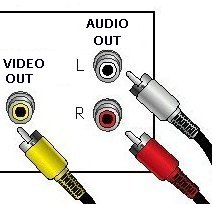 
Cables from OUT jacks going to IN jacks
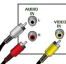
Your TV gets its INPUT from a VCR, DVD player, Cable TV converter, an
antenna, as well as other components, all of which send signals to the
TV's VIDEO IN and AUDIO IN.
So, you will want to connect a cable to the TV
INPUT jack.
Now, which cable and which jack? A TV set typically has to have sound and
picture. To get sound (audio) signals and picture
(video) signals IN to the TV, you are usually given several
options. Newer TV sets have multiple ways of getting signals IN, while
older TV sets may only have one way. The choices of which connection to
use also depends on what jacks/sockets are available on the TV and the
component you are connecting.
There are often many ways of accomplishing
the same goal. A TV for example, can be connected to a VCR by an RF coaxial
cable or it could be connected by a composite video cable and two stereo
audio cables. The only difference is quality. The coaxial cable connection
is lower signal quality.
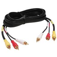
Video cables and audio cables used to connect components come in a variety
of types. Each type carries a signal, but because signals are processed
differently by the various component's internal circuits, different
connectors and different cable elements are used. You need to become
familiar with the various types of cables. Learn the colors and shapes of
the connectors and jacks/sockets. The color of the connector (male)
usually matches the color of the jack (female).
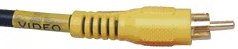
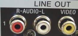
RCA Connector (composite video cable)
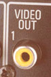
RCA composite video jack
Audio / Video Connector and cable types
There are many ways to connect audio and video components. You will be
limited sometimes in your choices depending on what connection jacks are
available on your components. The chart below summarizes some of the
common cable
connections for audio and video.
| Connector Type |
Cable |
Quality |
Used On |
| RF audio and video |
1 cable 'F' coaxial |
Fair (analog) |
VCR, TV, Converter |
| Composite video |
1 cable RCA (yellow) |
Good (analog) |
VCR, DVD, TV |
| Stereo audio |
2 cables RCA
(red, white) |
Good (analog) |
VCR, TV, DVD |
| S-Video |
1 cable 4-pin |
Better (analog) |
TV, DVD |
| Component video |
3 cables RCA
(red, blue, green) |
Best (analog) |
TV, DVD, HDTV |
| Multi-channel audio |
1 cable RCA or Optical |
Best (digital) |
DVD, A/V Receiver, Converter |
| DVI video |
1 cable multi-pin |
Best (digital) |
HDTV, Converter |
| HDMI video/audio |
1 cable multi-pin |
Best (digital)
|
HDTV, Converter, A/V Receiver |
| IEEE-1394 |
1 cable multi-pin |
Best (digital)
|
Converter, HDTV |
| USB |
1 cable multi-pin |
Best (digital)
|
Converter |
Audio Video Cables
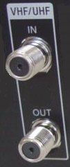
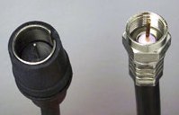
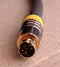
RF (radio frequency) 75 ohm coaxial connection
(see picture)

RF coaxial connections connect your cable TV or rabbit ears antenna to
your TV by a cable usually screwed (turned) or pushed on at both ends rather than just
plugged in like a RCA type connection.
This connector type was originally designed to accept radio
frequencies via an antenna or RF cable (cable TV) connection. This is the
lowest common denominator for connecting analog video to a TV.
Only VCRs and DVD recorders can be connected via the RF connection. A VCR outputs to
channel 3 or 4 on the TV.
Currently, not many
DVD players on the market support an RF coaxial connection. Because of
lower signal quality, RF coaxial is generally not the recommended way to
connect video equipment to your TV. Audio and video are
both carried together on
this type of connection.
Composite video connection

A common method of connecting TVs and video equipment together
is the composite connection. The connector is usually yellow and accepts an RCA-style
plug. Composite is the lowest common denominator connection type for DVD
players.
Unlike RF cable connections, which carries both audio and video, composite
connectors carry video only. Use (2) audio RCA-style cables for
stereo sound when using composite video connection configurations.
S-Video (Super Video)

By separating the luminance (light) and the chrominance (color) signals
of a video signal, S-Video offers a higher-definition image and clarity
than RF or composite video.
This is one of the best ways to connect your VCR to your TV and the
second-best way to connect your DVD player to a TV.
However, in order to benefit from S-Video's higher quality you must
have a TV that has an S-Video IN jack (4-pins). Only video is carried on this
type of connection.
Component video (Y'Pb'Pr')
 |
Component video is one of the best methods of connecting a DVD player to a TV.
It is also a good way to connect a Digital Cable TV converter to a
HDTV. It separates the chrominance and
various luminance levels into three separate channels. Doing this
maintains a higher level of data integrity when the signal is passed over
cable.
The term Y'Pb'Pr' applies to the way component color video separates
color signals. Y' (luminance) is the brightness and darkness of the signal
connector. Pb' is Blue minus the luminance signal connector. Pr' is Red
minus the luminance signal connector.
Only video is carried on this type of connection. |
DVI

DVI is a video only connection used on digital TV displays,
set-top-boxes, digital TV tuners, and some DVD players. DVI is largely
being replaced by HDMI.
HDMI
HDMI hookup

The High Definition Multimedia Interface can carry video and audio.
Used on HDTV sets, DVD players and more recently A/V receivers this
connection is quickly becoming the standard in the digital component
arena.
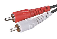
Stereo 2-channel Audio
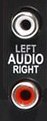
Stereo (red and white) RCA cables provide a means of connecting to a stereo receiver for
playback through stereo speakers. The color-coding on an RCA connector
applies red to the right audio channel and white for the left audio
channel.
If your TV offers only one audio jack, you would use only the white
plug on the stereo RCA cable to provide mono sound through both speakers.
Only audio is carried through this type of connection.
Component analog audio
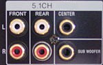
You will find these types of connectors only on DVD players that have
built-in Dolby Digital or DTS decoders and also on SACD players. These 6 plugs are directed toward a
5.1 surround-sound setup.
You must have an A/V receiver capable of accepting 6 signals and also
have surround-sound speakers attached to your system. This type of
connection is for audio only. The 6 cables are for speaker channels
left-front, center, right-front, left-rear, right-rear and subwoofer and
have RCA connectors.
RF digital audio output (SPDIF)

RF digital audio is designed to output Dolby Digital or DTS audio from a
DVD player or laser disc player in a digital form. This provides higher clarity
and expanded audio features such as Dolby Digital.
To use this feature on a DVD player you must have an A/V receiver
capable of accepting a signal that can either decode the signal itself or
output to a decoder box that can.
You will also notice that an RF digital connector looks a lot like a
composite connector. Do not confuse the two. When in doubt, double check
-- the jacks are usually labeled and/or color coded. The color orange
is often used on the jacks for digital audio (RCA connector). The jack is
usually labeled COAXIAL and uses the Sony Philips Digital Interface.
Digital audio output (SPDIF)

Digital audio (SPDIF) serves the same function as an RF digital audio
connector but with a slight difference: The connection is for a type of fiber-optic
cable (Toslink). To benefit from a digital audio (SPDIF)
connection you must have an A/V receiver that has a digital SPDIF
connection with fiber-optic connection jack. Most new A/V receivers have multiple
fiber-optic jacks. Usually black in color. Use either RF or optical cable,
both are good. You only need one or the other for passing digital audio to
the A/V receiver.
VCR DVD Recorder and TV Connection
Here are some general guidelines for connecting a VCR to a TV:
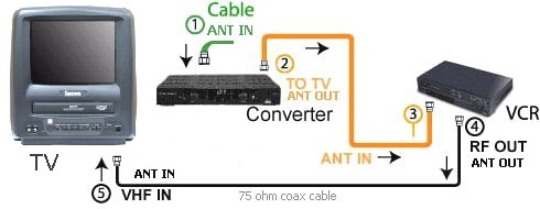
- One way to connect a VCR to a TV is to connect its RF coaxial
output
connection to the RF coaxial input (antenna) connection on your TV.
To do this, attach your antenna or cable TV feed
cable into the VCR's RF
coaxial input connection. This will allow you to record one show on the
VCR while your TV is tuned to another station.
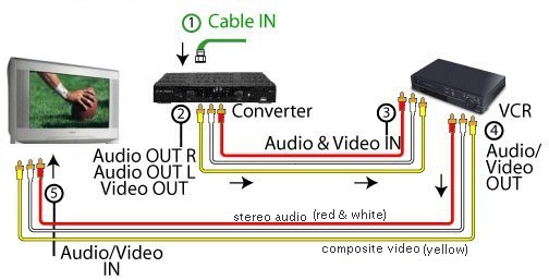
- Another way, is to connect your VCR via its composite video or
S-Video output connection to your TV's composite video input or S-Video
IN jack.
You need two antenna or cable TV feeds, one for the TV and one for
the VCR, if you want to watch a show on the TV that is different from
what the VCR is recording.
You will also need to attach stereo RCA cables in order to get audio
from the VCR. You can attach either to your TV, if your TV has audio RCA
input jacks, or use your home stereo. See TV-VCR
DVD and TV Connection
You can connect your DVD to your TV either via its composite video, S-Video
or component video connection. Your TV must support a composite video, S-Video,
or component video input. If it doesn't, you will have to buy a composite-to-RF converter for
your TV connection. An RF converter can degrade the video signal and provide a poorer
picture. For audio you need to attach stereo RCA cables from your DVD
player to your TV or, if your TV lacks these inputs, to your home stereo.
DVD, VCR, TV Connection
Here are some general guidelines for connecting a DVD and VCR to a TV:
- If your TV has both an RF coaxial and composite video connector:
- Attach the VCR via its RF coaxial connection to your TV.
- Then attach your cable TV or antenna to your VCR. Connect your DVD
player straight into your TV via its composite video connector.
- Attach the stereo plugs either to your TV or your home stereo.
If your TV lacks these inputs try using your home stereo.
- If your TV has only an RF coaxial connector:
- Attach the VCR via its RF coaxial to your TV.
- Attach your cable TV or antenna to your VCR.
- Now connect your DVD player to your VCR's video input
connection.
•
How to Connect
your DVD player
You can connect your stereo audio cables from the DVD player through the
VCR and from there to your home stereo. You can also connect the stereo
straight from the DVD player to your home stereo. To watch your DVD you
need to set your VCR on video input selection.
A word of warning: Because of Macrovision, not all VCRs allow
you to pass through a DVD signal.
Macrovision is a technology that disallows the ability to copy a
commercial VHS or DVD video onto VHS tape. It is built-in on most consumer-level VCRs and DVDs.
Some VCR manufacturers have not implemented this feature correctly.
Because of this, pass-through video from a DVD to a VCR may come out with
a garbled image. Ideally, Macrovision should only affect a VCR's record
function.
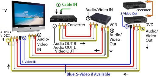
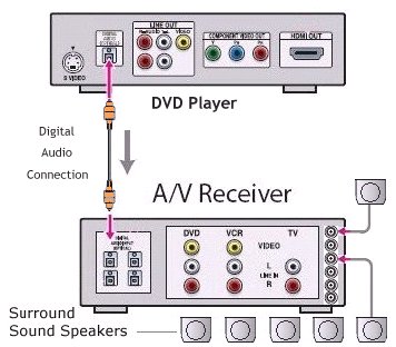
DVD, VCR, TV cable connections to Audio / Video Receiver
Depending on your connection options there may be several different
ways to configure a DVD, VCR, TV, to an A/V receiver.
Here's is one way you can configure all these components
together.
- Look at the back of your A/V receiver.
You'll notice a large array of video and audio inputs and outputs.
Each one has a silkscreen name either directly above it, below it, or
next to it.
- Look for the video output that says "monitor output" or something
similar on the back of your receiver. Connect the monitor output on your
A/V receiver to your TV's S-Video or composite inputs.
Doing this will only allow you to see a picture. Also notice a
section on your A/V receiver that has a set of jacks for TV satellite
inputs as well as an RF coaxial connection for a cable TV, antenna, and
satellite TV.
- Attach your VCR to the one of the video inputs in the back. Most A/V
receivers have at least two of these inputs. They usually look like
Video 1 input/output and Video 2 input/output. Use Video 1.
- There are jacks for inputting composite video and/or S-Video and
stereo left and right.
Connect your VCR's composite or S-Video and audio output to these
inputs. Then from the same Video 1 section on the back of the A/V
receiver you will also notice another set of jacks that are labeled
outputs. Connect these outputs from the A/V receiver to your VCR's
inputs.
Why?
You are equipping the receiver to both take and send signals to your
VCR. This way you can both record and playback from your VCR through
your receiver.
- Attach a DVD to the Video 2 inputs. Again, connect the composite
video or S-Video outputs of your DVD player to the Video 2 composite
video and S-Video inputs.
- Do the same thing with the audio outputs. You can either use the RCA
stereo plugs or the digital audio connections, if your stereo supports
them.
•
See over 50 Wiring hook up
diagrams
•
Home
Theater Connections
• Cable Types - an explanation.
|