Aluminum Mold
This project arose from my experience trying different mold materials. Each one I tried had some benefits and some drawbacks.
The first thing I tried was plaster. It has the benefit of being low cost and easy to work with. The drawbacks are that you can't adjust the mold and there's a limit to how good a finish you can get.
The next thing I tried was an epoxy mold. This has the benefit of providing a finish as good as the plug, but takes a while to lay up. I tried pouring epoxy with no fiber reinforcement over a plug mounted on a sheet of glass to create a flat mold. This resulted in a mold with good finish, but lack of stiffness. I supported this on a plaster base which had the tune I wanted. This worked pretty good, but I destroyed the mold when I stuck a boom in it.
In an effort to get both the ability to adjust tuning and good release properties I tried silicone rtv. I supported this on a plaster base as with the epoxy mold and it worked great from an adjustment and release perspective. The drawback with it was that when I clamped down the pressure to squeeze out the extra epoxy, the rtv would "give" and the kevlar weave would "print through" and be visible in the finished boom.
My wish list was growing. I wanted a mold that I could adjust, so that I could iterate on tuning without having to make a new mold each time. I wanted a mold that had good release properties, or was strong enough that I'd destroy the part and not the mold if something got stuck. I wanted a mold with a hard surface to eliminate print through and yield a glossy finish.
I had also been working on making Rohacell cores for my booms and had found that thermoforming them worked out to be the best approach. I was using JB Weld to make a mold that could withstand the 400F temperature needed to thermoform. This worked, but was not an easy material to get a good mold from.
When I added temperature resistance to the other list it really eliminated a lot of materials, leaving mostly metals. I decided that I would try to find a way to make a mold from aluminum. After some research into various methods of forming aluminum I decided I would try to make a CAD model and have the mold cavity machined from sheet stock.
After some trial and error with different CAD packages and a lot of experimentation I decided to use a package called Rhino3D. This package excels at the creation and manipulation of surfaces, which is what I wanted to create.
I began by creating an outline of the shape. Rhino has a way to let you put a jpeg image in the background and scale it to help your design efforts. I started with a scan of a Jonas. I created curves that followed the contour as a starting point, then used the package to "fair" the curves so that they flowed. This altered the outline of the boom subtly at the elbow and tips.
Once I had an outline, I created the airfoil cross-sections that I wanted: one for the elbow, one for the wings. I scaled and placed these at key points, then "lofted" a surface through them. The next step was to fair the surface and get things like the tips and thickness adjusted just right.
Enough boring text, now for some pictures!
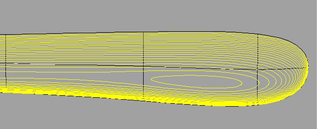
This is detail from a contour diagram of the surface of the mold. It's a right-handed design, and we're looking at it from the bottom. Each line represents .0025" of height. Click here to see the whole diagram.
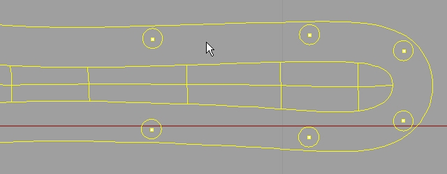
This is detail from a drill template. There's a "collar" added around the mold cavity for mounting. Click here to see the whole diagram.
Now I had a model of the mold and needed a way to get it machined. The next step was to find someone with the right equipment to machine the mold. I tried a number of avenues for doing this, including talking to the shops at the local university and technical schools. All of these turned out to be dead-ends. The machine shop at the technical school had some interest initially, but decided they'd pass after they looked at the model and realized there wasn't a single flat spot on the whole thing.
I was at a bit of an impasse until I got a generous offer of help from Jonas Romblad and a couple of his coworkers. They had the equipment, they had the know-how, they had the interest. So I sent them the file and waited to see what would come of this international cooperative effort...

I recall this very clearly: I was having an especially crummy day right up until the point where I got home and found a triangular package at my doorstep with these words on it. Needless to say, things started looking up at that point!
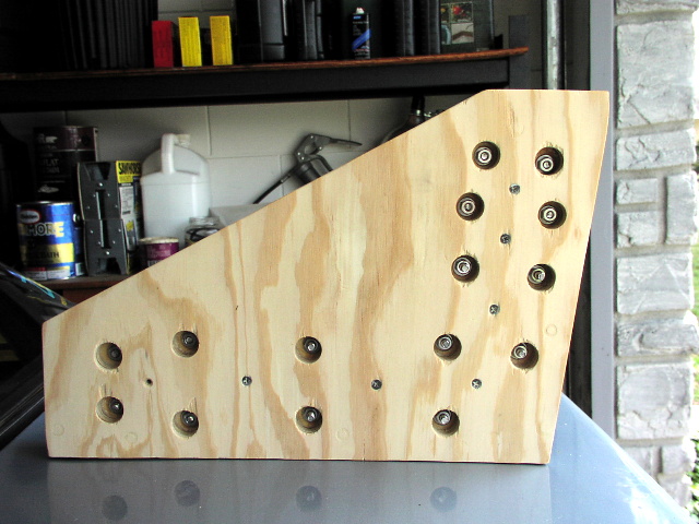
Inside the package was the mold. This is a picture of the back of the mold, showing how the finish looked before I started sanding and polishing. It has a bit of heat discoloration because I used it to thermoform cores before polishing. The mold is machined from 4mm thick sheet stock. The machining process left the mold cavity with a texture that could be felt, tiny ridges that needed to be removed to get a glossy finish.
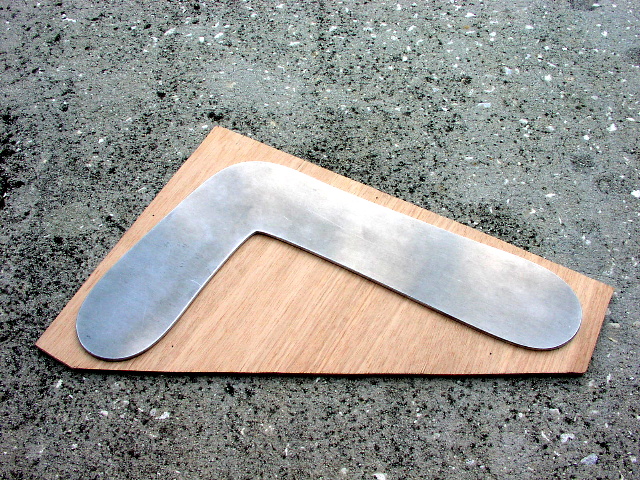
Here's what the top of the mold looked like after about two to three hours of sanding and polishing. All finishing was done by hand, no power tools.
Fred Malmberg gave me some great advice on sanding and polishing that helped shorten the learning curve. My favorite bit of advice was to wear gloves when wet sanding the aluminum, so that your hands don't turn gray. If he hadn't mentioned it, that's the first thing I'd have learned, the hard way!
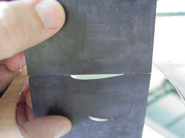
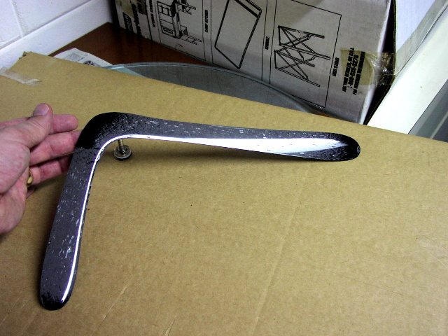
I'm holding a piece of cardstock that's painted black to show what the typical cross-section looks like. One of the things I learned is that it's really tricky to get good pictures of a mirror finish...
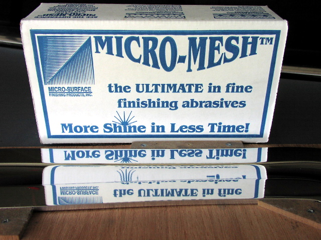
First step in getting the mirror finish was to use Micro-Mesh abrasives. These sheets start at 1500 grit and go to 12000 grit. I wet sanded about 15 minutes with each one.
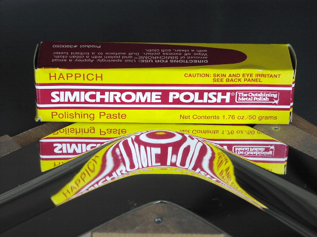
Between steps I used Simichrome metal polish to clean things up and check progress. The final polishing step was with Simichrome as well.
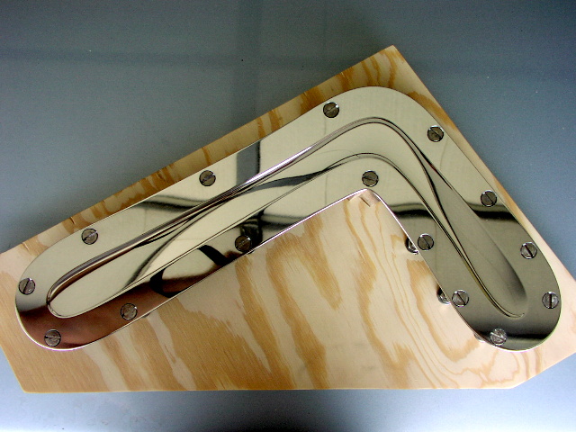
Top view of polished mold. It has been drilled and mounted on top of two layers of 3/4" plywood.
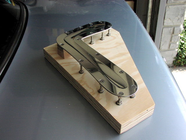
End view of mold. You can see that the elbow is supported on 1.5" square hardwood stock. This holds the elbow flat to form a plane of reference, the rest of the supports are adjustable.
Bottom view of base, showing how the nuts and bolts are countersunk so you can sit the whole assembly on a flat surface after adjustment.
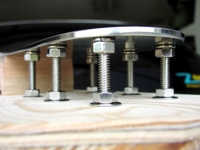
End view showing detail of mounts. Each mount has a nut that clamps it tightly to the mold, and a nut above and below the base. You can adjust each mount so that it pushes or pulls the mold to get whatever dihedral and angle of attack you want. At 12 threads per inch, a quarter turn is about .020" of adjustment. The nuts above and below the base are tightened against each other to create a firm base, then tightened or loosened on one side or the other to tweak things into final position.
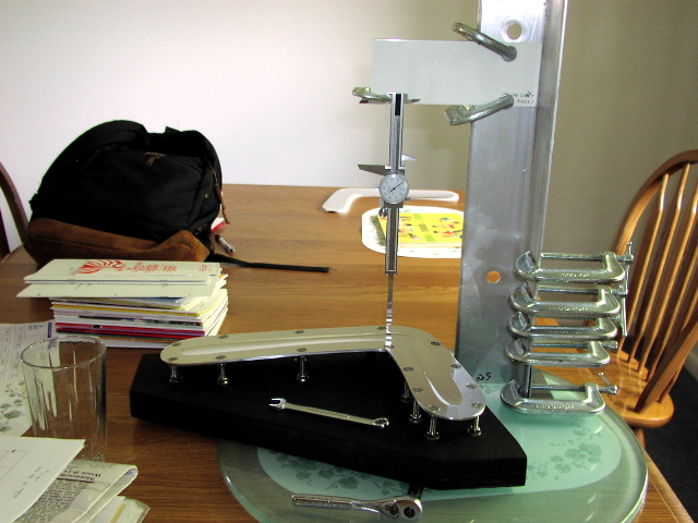
Here's the setup used to adjust the tuning. A glass tabletop gives me a nice flat reference. A caliper is clamped to a big piece of aluminum angle stock, and is used to measure the height of the mold at different points. Discussions with Jonas helped get the initial tune in the ballpark.
Even though it doesn't look it, with careful use this setup can measure to within .001". Remember: with enough clamps, you can do almost anything! :)
I painted the base black because I thought it would look better, but I think I liked the contrast of shiny aluminum and wood grain better than shiny aluminum and flat black paint.
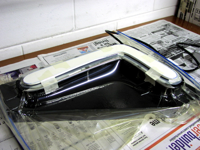
Mold with boom layed up in vacuum bag. I tried to bag just the top of the mold, but had problems getting a decent seal, so I went with bagging the whole thing instead.
First boom from mold. A few surface defects, but not bad for a first effort. Weight was 12.3 grams.
I still have some fine-tuning to do, and some learning to get a flawless finish, but the experiment has been a big success already. This approach is resource intensive, but it meets all my wish list criteria.
I can think of other benefits as well: 1) it is possible to email the mold halfway around the world and create an exact copy, 2) it is possible to make additional copies of a mold to replace a damaged mold or increase production, 3) it is easy to make identical RH and LH booms (just mirror image the model), 4) it is possible to make small, controlled design changes to the profile and airfoils of the model, 5) physical properties of the design (area, volume, center of gravity, moments) are easily obtained.
The next thing I'd like to try is making two molds: one for laying up the boom, and another for thermoforming the core. It's possible to use the skin mold to form cores, but the core needs to be somewhat undersized so that it just fills the cavity without increasing the finished thickness. Cores made using the skin mold require some delicate sanding afterwards to reduce the thickness. In addition, once you've got the skin mold polished, mounted, and tuned it's not desirable to tear it down to make more cores.