| XMODS EVOLUTION DEANS 5 - DEANS 6 - DEANS 7 CELL TUTORIAL |
| PART 2b: INSTALLING THE CHASSIS PLUG - CONTINUED |
| If you have any questions, please email me. [email protected] |
 |
 |
 |
 |
 |
 |
 |
 |
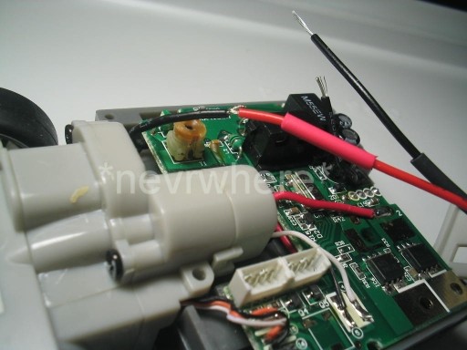
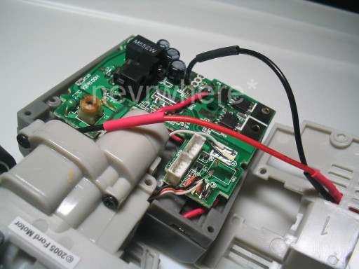
| Twist the red wire of the chassis plug with the cut end of the black wire closest to the front of the car (the wire that leads to the cars stock battery holder). |
| Twist the black wire of the chassis plug with the black cut wire that leads to the circuit board. |
 |
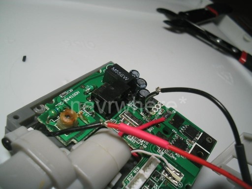
| Slide the heat shrink tubing over the twisted wire connections. |
| If you want, you can now solder the wires together for added strength, but it is not necessary. |
| Use a hair dryer to shrink the tubing around the connection. |
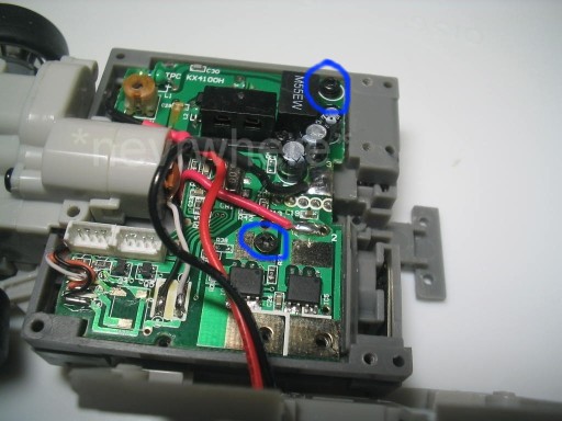
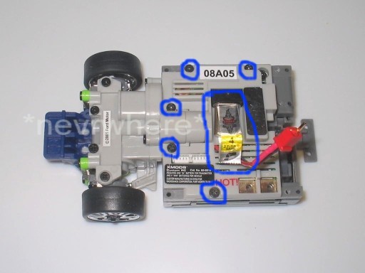
| Replace the antenna screw and the circuit board securing screw. |
| Replace the circuit board cover and screws. Replace the crystal. |
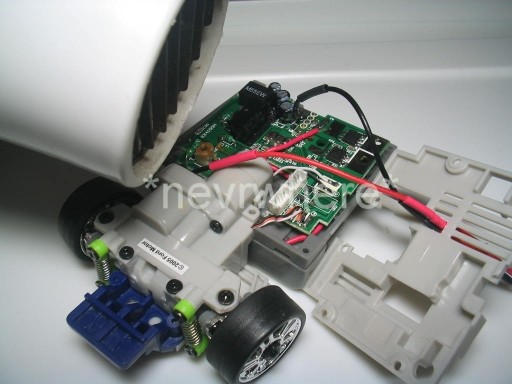
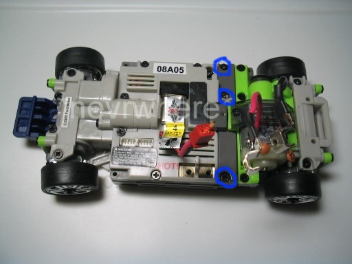
| Re-attach the rear end. Replace the 3 screws on the support beam. |
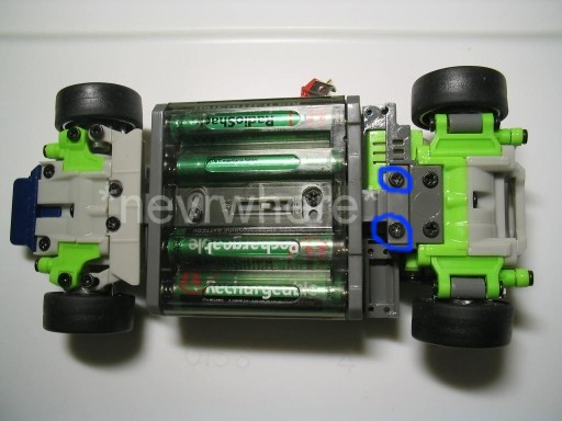
| Replace the T-bar screws. |
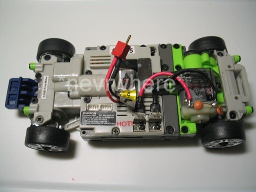
| There you have it. All assembled and ready to plug in your 5 or 6 cell hop-ups. |
| When replacing the cover, you will have to manuever the wires around so that they will lay flat against the board as you put the cover on. Just make sure it does not interfere or block the area the crystal will go into. |