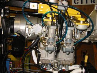
I had to move the engine about 1 1/4 inches to the rear and I still could only get it down to 3 degrees because of problems getting clearance for the prop. ( This explains why I moved the battery forward.)
I am using a 3 blade Warp Drive prop that is 66 inches in diameter.
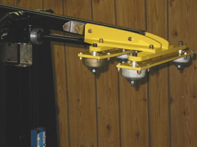
All pieces of the mount shown here in yellow are made of 6061 Aluminum. Two, 3 inch aluminum angles form the basis for this mount.
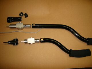
The pivot bolt that ran thru the stick had wallowed out the hole giving play in the controls.
I wanted to make the rear seat stick easily removable for taking some passengers, and it makes getting into the rear seat easier. I can also carry more cargo, as when I need camping gear.
I made these machined parts to solve the problem, but if the factory was smart, they would Loc-Tite a slug into the stick before they form the end. I think this would solve the problem.
Photo shows the parts I removed.