
What I'm getting at is that the 510 just can't go wrong from contributions from the Z family of cars. Heck, they were Zs in sedan form (although the 510 did come first - chicken and egg argument).
Have you ever owned a first generation Z and just couldn't get over the ergonomical genius inside. Everything is comfortably accessible. This is were, in my opinion, the 510 failed:
To get to the point, this article will help walk you through the upgrade of your internal switches and wiper motor to a cooler Z column mounted switch stalk and Z 3 speed wiper motor with intermittent relay. Understand, that I am by no means an electrical demigod, heck I don't know what I'm doing half the time, but this works, so...
Before you get started there will be some things that you will need:
I started my mad experiment by enlarging the wire diagrams for the 510 and the applicable Z donor via photocopier. The result was two diagrams about two square feet that I didn't have to squint over. If you should ever do this, do yourself the favor of coloring the wires with colored pencils. A major time saver.
Now I have to explain a few things in order to make you understand the method to my madness. Whenever I perform any modification, I like to leave the option to go back to stock. This means that I typically incorporate as much of the stock assemblies available. Therefore, this modification will not require you to hack up the stock wiring harness - at all. However, the implication is that you must be able to provide extra connectors for the headlamp and wiper connections. If you can't locate extra sets, don't sweat it, just use the ones from the car's original set. I'd recommend removing them by loosening the solder at the switch, that way it can be a clean restoration if you decide to later on in life.
Another tip for a clean finish is to stagger, or offset, your splices on any one harness. The reason for this becomes evident when it's time to wrap the harness and you end up with this big wrapped up lump mid harness that resembles a boa constrictor that has eaten a cat. Also for a clean job, I recommend intertwining your splices end to end, just as you would intertwine your fingers if you were to place your hands on your lap. These are merely techniques, and remember, how you choose to do it is up to you.
Ok, ok! Get to the point.
Modifying the Z Wiper Motor:
Begin by unwrapping the Z motor from the protective vinyl bag it comes in. The reason the factory did this is because the motor sits out in the open on the Z, but it's under the hood in the 510..so shuck it! Next, remove it from the bracket that attaches it to the car. You won't need this either. Finally, you can toss the swing arm on the Z motor spindle. It's offset for the 510 and the stud is too large for the 510 linkage.
In order to remove your 510 wiper motor, you will need to remove the cowl in front of the windscreen. This is a good time to clean out the tray of leaves, needles, bugs, etc. Take a coat hanger and run it down the center drain to clear it out. When it comes time to reinstall the cowl later on, do yourself a favor and lay some stainless screen beneath the cowl to prevent debris from getting back into the drain. This will save your car from rust problems, if they haven't already started down there.
There will be a tricky clip on the wiper arm connected to the linkage. Patience and some fingernails will help pop up the clip. You will feel that it must be lifted and slid off.
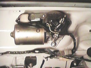
Before dismantling the 510 motor, scribe a line that indicates the clock
position of the wiper motor swing arm in relation to the base. You
will want to have the arm in the same position on the Z motor. See
photos.
 |
Notice that the swing arm is in the 8 o'clock position. This is the only position that will work - trust me on this. The reason is simple - it's the apex of the wiper's spin cycle. There is no way to get around it, as I'll explain later. |
 |
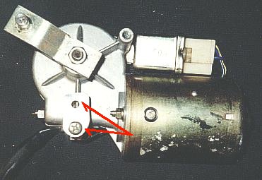
510 motor. You will want to use the harness from the motor to wire the Z motor. |
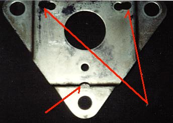 |
This is the 510 wiper motor base plate. The important thing here is that you make sure that the Z motor spindle is centered on the base. In order to mate the Z motor to the base two holes will be required along with a cut away indent at the bottom. |
 |
The nice thing about the Z wiper motor is that it lived it's life in
a vinyl bag, thus preserving it's finish. People will think you went
all out and bought a new motor!
In order for the Z motor to fit onto the 510 base plate, a tab will have to be made that offsets the bottom screw. I made mine from 1/8" aluminium sheet, you could cut one from the Z wiper motor base before you toss it. The relay will need to be unscrewed when it comes time to install the motor to the 510. The 510 arm is fit onto the Z motor in this photo. |
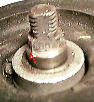 |
The spindle on the Z motor is too wide. This will require some calculated filing in order to maintain the profile to fit the 510 arm. It's easy, just take your time or you'll cut to much to soon. |
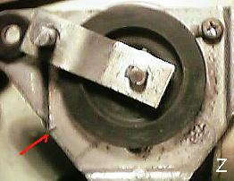 |
With the 510 arm fit to the Z motor, the swing arm ends up in the 10 o'clock position. If you ran this on the 510, wiper arms will always park about four inches from the bottom. As an added bonus, the wiper arms will start in reverse before going in the right direction (remember the apex thing?). Not real conducive to safe driving and defeats the purpose of the retrofit. Note the scribe on the base plate referencing the 510 arm position. |
 |
The 510 arm. |
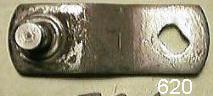 |
The 620 arm is the same length as the 510 center to center. The nice thing about this is that it puts the arm close to the stock 510 position. |
 |
When the 620 arm is mated to the Z motor, you can see how close it is to the proper 510 position. |
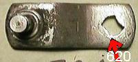 |
In order to get the 620 arm to work perfectly you will need to reshape the slot into an hourglass shape. This is where those tiny files come in handy. I didn't have a small flat file, and since it was the middle of the night, I employed some ingenuity and grabbed a metal blade for a saber saw with vice grips and patiently worked the slot . |
 |
All of your hard work will pay off in this form. A Z wiper motor that will work properly on a 510. The red line depicts the change in position of the 620 arm on the motor to it's final resting place. |
Modifying the Steering Column for Z Ignition Switch:
In order to mount the Z ignition switch onto the 510 steering column you will have to do one of two things:
1. Grind down the lip that holds the lock/switch in place on the column. This will disable the lock since there won't be a corresponding hole for the lock, or
2. Modify the steering column to accept the column lock on the right hand side. This is how I did it. I was fortunate enough to have extra steering columns from my donor lot of 510s. I went through two before I got it right. What you need to do first is measure the Z ignition switch in relation to the steering wheel and column cover. It should measure around Notice that you have to cut a circle and then a slot into the column layers. Use the dimensions from the original lock slots to cut the new ones. Take a piece of masking tape and make an outlined template from the original hole. Cut out the tape hole and set it aside. Once you have found the proper position for the Z ignition switch, mark the center. Now place the tape template centered over the newly marked spot. Scribe your new cut-out and carefully match the outline. After you cut out the first hole, place the 510 lock back in place and lock the column. This will place the original slot at 180 degrees from your new work, keeping the most amount of steel in the column between cuts. Mark where the new slot will be and then remove the column from the car. After you get the column out of the car, you will need a pair of snap ring pliers to disassemble it. Remove the inner rod and spring. This gives you a chance to clean out all of the metal shavings from the first hole you cut. About three drill holes will get you close before you will need to employ the rotary file. Patience is key, since you only get one chance to get it right (unless you have spare steering columns). Practice using the rotary file on scrap metal to get a feel how the drill will want to wander. Make sure to clean all burrs, since the inner column sleeve has a nylon liner that will get eaten up. Once done, clean, reassemble, and reinstall. Now to the electrics.
Modifying the Wiring:
This is the poor man's schematic. I will talk you through the wires from Z assembly to 510 harness. Before you cut anything pay close attention to every little detail that you can. Write things down before you act. The reason is clear - the wire colors change as they pass through connectors on harnesses. Notice how the 510 switch wires are all black?! The Z colors change as they go from switch to harness to relay/motor. Example: there are three black wires into the Z motor and blue/white becomes yellow/green!
All of my wire connections went from the Z stuff into the 510 wire harness
as much as possible. That way you don't have to cut up the 510 connectors
on the interior harness. This will require you to use the connector
end that is attached to the switch, however. That is why I recommend
finding donor switches in order to keep the stock switch in case you decide
to go back to stock. As I explain the splices, remember that the
donor connector wires will not match my description. Just connect
the donor connector to the 510 harness and walk the color from the switch
wire to the 510 harness. It will make sense when you see it.
Description of wires:
Colors (in accordance with Nissan, oops, I mean Datsun):
Headlights:
Z switch Big R connects to
the 510 RY
Z switch Big WR
connects to the 510 WR
Z switch GL
connects to the 510 GW
Z switch GW
connects to the 510 GL/GW
Hi Beams/Turn Signals:
Z switch WR
connects to the 510 BR
Z switch WB
connects to the 510 GR
Z switch WR
connects to the 510 GB
Z switch G connects to the
510 G
Leave the Z switch RY
unconnected. If not, you're hi beams will go screwy.
Horn:
Z switch GB and connect it to the 510 BG
Hazard Switch:
The 521 hazard switch connects directly to the 510 harness without modification. If you can't find a 521 switch, you simply have to find a place to mount the stock 510 switch.
Z Wiper Motor and Intermittent Relay:
Z switch LR
to LR
on 510 inside interior harness y-spliced to LR
on the relay to and connect it to Z motor LR
Z relay Y connects to Z
motor Y
Z switch LW
connects to Z relay YG
connects to Z motor YG
Z switch LY
connects to Z relay LY
Z motor YB
connects to Z switch L
Z switch L connects to Z
relay L
Z switch B connects to 510
harness B
Z motor LY
connects to Z switch RL
510 Harness to Z Motor:
LY
510 harness connects to LY
on Z motor
L 510 harness connects to L
on Z motor
LW
510 harness connects to YG
on Z motor
You will want to use the connector that is on the 510 wiper motor on
the Z wiper motor. This will allow you to run through the fuse block.
Two wires will not fit into the 510 wire harness leading out to the Z motor.
That will require you to run those wires through the firewall to the motor.
I had an extra two wire connectors that I spliced into the Z motor harness.
This makes it non permanent, thus allowing you to remove the motor without
having to cut wires.
Enough Talk - I Understand Pictures!
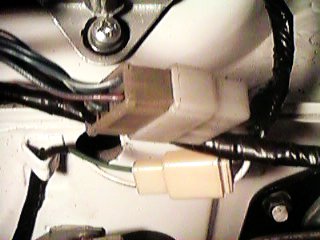 |
The top connector is coming from the under hood harness (stock) to the wiper motor. The additional two wires required were run through the firewall and into a scrap connector set I had and into the motor. |
 |
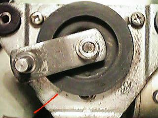
Here you can see the Z motor in place and the way the final wiring lays into place. |
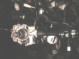 |
This is how the switch assembly will fit onto the column. |
 |
I tucked the intermittent relay inside the dash behind the gauge cluster. I drilled a hole into the dash support bracket in order to secure the relay. You should have enough wire to accommodate it. |
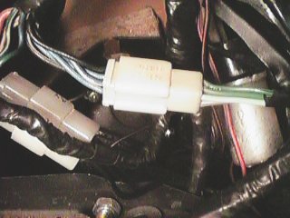 |
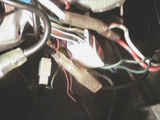
Here's a shot of how I integrated the existing wire connectors with some matching scrap connector ends. The one on the right is the wiper and the one on the left is the headlamp wiring. Makes for a cleaner fit. NOTE: colors in do not match colors out. Watch what you're doing and attention to detail will pay dividends here. |
 |
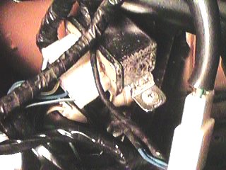
Just another wire bundle - this is on the column. |
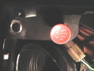 |
The cool thing about the old pickup hazard switches is that they fit like the 510 headlamp/wiper switch. Since you'll end up with a couple of holes where they once were, why not jam your new hazard switch there too. You'll have enough stock wiring to reach the old wiper switch location. The connector matches, too! You can use the other location to run fog lamps, etc. using a similar pull switch. |
I've yet to modify the the steering column facia to cover the top of the column. I plan to use fiberglass, and will publish the results when complete.
Well, I think that's all I can think of, although I know I've forgotten some things. More pictures will follow. Feel free to email me with questions relating to this upgrade at [email protected].