Haley Turbine Projects


|
Haley Turbine Projects
|
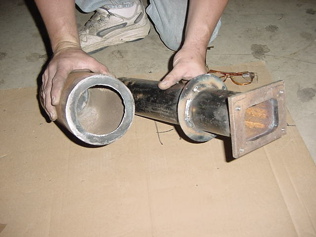
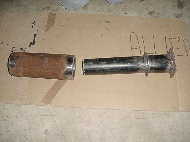
Made the combustor/turbine flange, air casing, flame tube, and sealing flange after work today. Made the casing out of 5 inch I.D. tube and the flame tube out of 3-1/4 inch O.D. tubing. The flange is 1/4 inch plate steel. I love to build and weld these things but I dislike gathering and cutting the steel in preparation for assembly.
After work Rob and I went to the shop to clean the flanges and continue assembly of the combustor. We welded the sealing flange on the flame tube and the air casing. We welded the top of the air casing to the air casing cylinder. The next step in to design the injector assembly and igniter.
Air casing and flame tube
Insert info soon
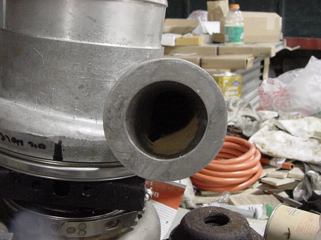
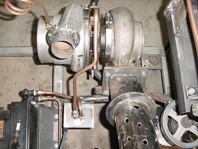
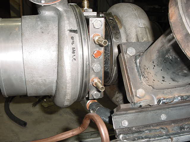
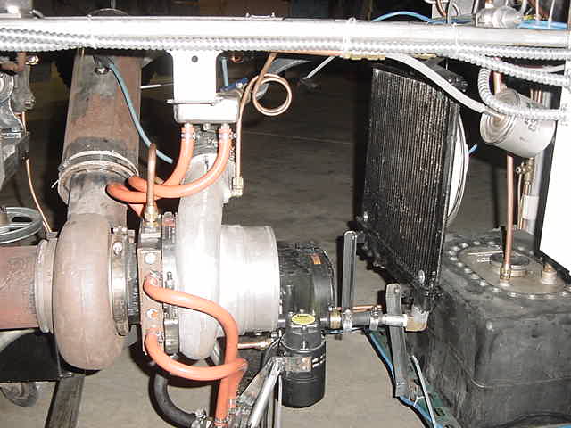
I took the turbojet to a muffler shop today. They made a tube to fit the compressor and the air casing. They did not charge for this! Thanks Gary and Charlie. After work Rob and I went to work on the turbine. We started by cutting the original compressor flange from the housing. Then we made a flange for the air delivery tube to mate with the compressor flange that we had fashioned from the remaining aluminum. ( see photo ). I drilled and tapped hole in the compressor flange while Rob disassembled the combustor on HT1. With the air tube fastened to the compressor, I welded the tube to the air casing.
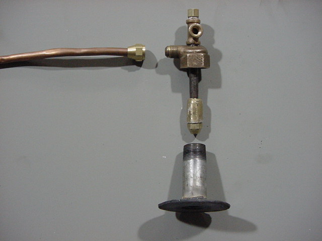
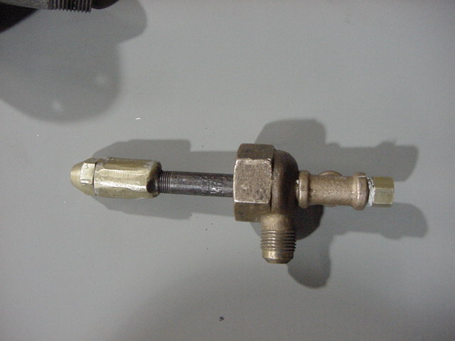
Flange for air delivery tube off compressor Air delivery tube After the air casing cooled, we removed the fuel injector flange to complete the construction of the injector module. The injector module is also the air casing retainer. We took an oil burner nozzle holder and tapped the back of it to accept a 1/8" pipe nipple. We are trying something different by plumbing primary air into the cap of the injector module. The air will come down the tube that surrounds the pipe nipple and fuel nozzle, exit around the fuel nozzle to aid in combustion. We will control the amount of air through the module with a ball valve. This will also keep the module cooler. The copper line on the left will be bleed air that will be introduced into the flame tube around the injector nozzle.
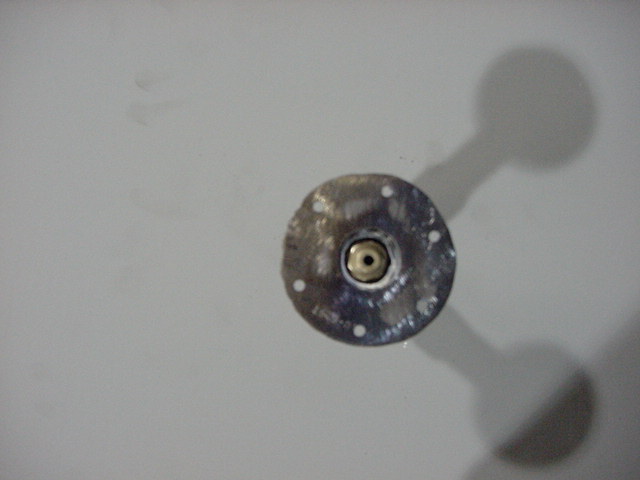
Exploded Injector Module Injector Assembly Bottom view of nozzle with air gap
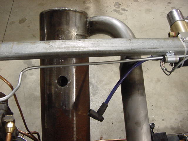
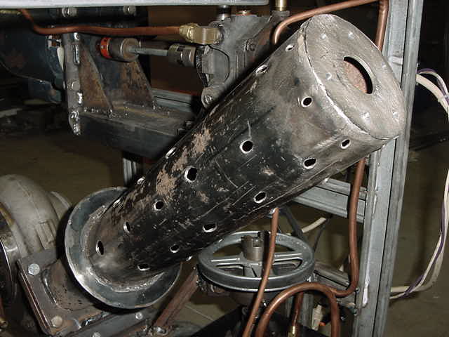
Today I worked on the turbine center housing flanges, flame tube, air casing and removed HT1 from the test stand. The first thing I did was make the igniter flange in the side of the air casing. I took a short piece of 1-1/8" steel tube and weld a 1/4" plate in one end of the tube. The plug had been drilled and tapped to accept an automotive spark plug. This was the same way I did it on HT1. Then I drill a 1/4" pilot hole through the air casing and the flame tube. The air casing is drill to the outside diameter of the 1-1/8" tube. Then the flame tube was drilled to accept the protruding electrode of the spark plug ( with a little extra room around the electrode to allow for thermal expansion of the flame tube). The 1-1/8" tube is welded into the side of the air casing and ground to the exterior contour of the casing. The next order of business was to make the flanges for the oil delivery and drain ports, water delivery and return from the center section of the turbine housing. These were made from 3/16" x 1" steel strap. The flanges were drilled for the mounting bolts, appropriate fittings and tapped for the fittings.
Spark Plug Port Then I drilled the holes in the flame tube. I was conservative on the amount of holes to start with. I can add more holes in the future. I started with (8) 3/16" holes around the fuel nozzle 1/2" down from the top of the flame tube for primary air. 4 9/16 holes were drilled 1/2" from the other end of the flame tube for the final dilution and cooling air. The rest of the holes are are various sizes and locations. (See photo). The air delivery tube was cut next and I remove 1/4" for an expansion joint. A rubber hose will be clamped over the joint. This will also allow quicker air casing removal and thermal expansion.
This is the first set of holes in flame tube Compressor and lower air casing flanges
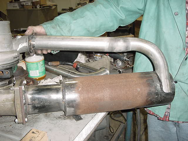
Today we finished the the assembly of the turbine. This includes the mounting of the oil and water flanges on the turbine center section. We welded the bracket to the combustor/turbine flange that allows us to bolt the turbine to the test stand mounts. The oil delivery and drain tubes were made and installed as well as the boost pressure line to the gauge. We made the new high pressure fuel line to the injector module. The cap on the left side of the injector module will be compressor air to supply primary air around the injector. ( Future experiments)
Top of Combustor Oil Supply Flange (top) Water Supply Flange (Front)
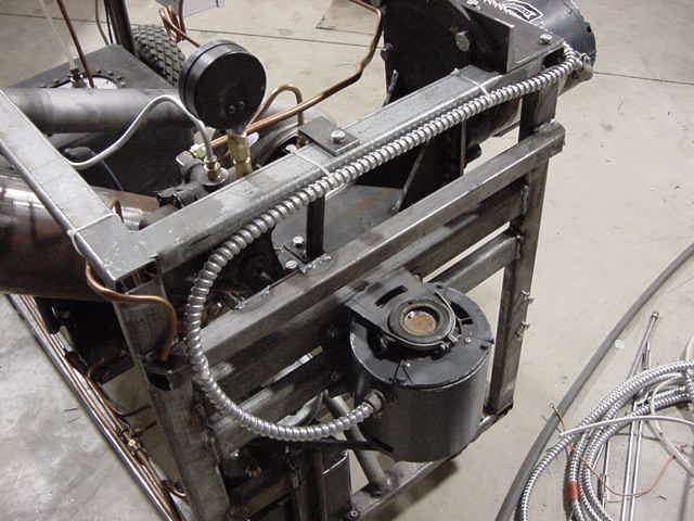
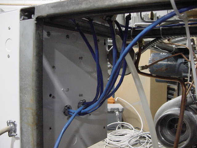
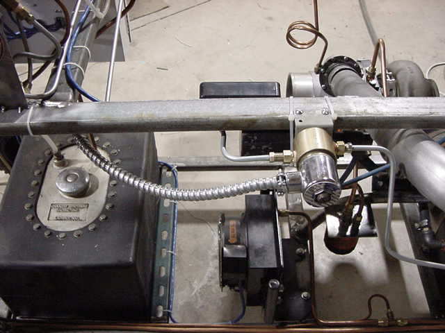
We started rewiring the test stand. I could not stand having to plug the fuel pump, oil pump, and the oil cooler fan into an extension cord to turn these item on. So we install a cabinet in which we home ran all our wiring for the various controls. The cabinet also contains electric motor relays that are controlled by switches on the instrument panel and a low voltage power supply. Now, when finished, the test stand plugs in with 1 power cord and power is distributed in the cabinet. We also placed all 110 Volt power is in conduit.
110 volt wiring placed in conduit Wiring into back of cabinet, 110 supply on left
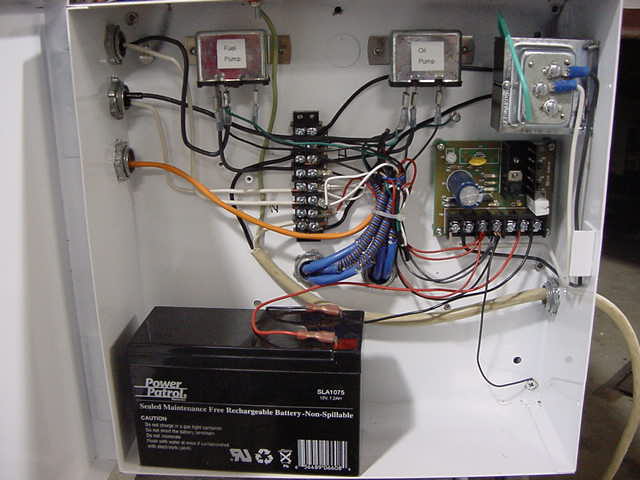
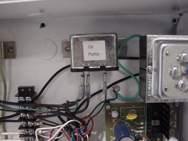
I finished the wiring of the test stand today after work. What a difference being able to shut off everything from the control panel. All of the wiring is in conduit or blue jacketed multi conductor cable. The whole stand looks a lot neater now!
Inside of control cabinet Oil Pump Relay
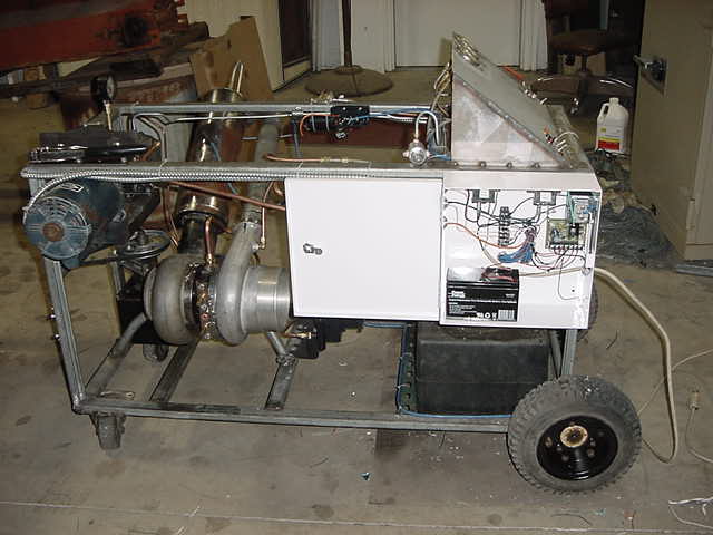
Fuel Cell, fuel shut off solenoid and oil cooler Side view of test stand and control cabinet
Started the turbine today for the first time. Installed an 8GPH 80 degree semi-solid nozzle for first try. Extremely hard to start. Flamed out before self sustain speed was reached. Then I moved the injector 1.25" deeper into the flame tube. Started easier but still flamed out and never seemed to clean out excess fuel. Too much flame from the exhaust during start up. Never did reach self sustain before flame out. Next I install a 5GPH 60 degree solid nozzle. Still had excessive flame from exhaust. Then I changed to a 5GPH 90 degree solid nozzle. Still had excessive flame and flame out but did self sustain for about 30 seconds. Now I will drill more holes in the flame tube. I have never had so much trouble starting one of our turbines before. I started with a small amount of holes to begin with intentionally. This way we could add holes and experiment slowly. I just got plain lucky on my HT1 flame tube.
I drilled more holes and enlarged some holes in the flame tube. I started out with the same 5GPH 90 degree solid nozzle. The turbine started and stayed running. I achieved 15 PSI boost at full throttle. Boy does this engine sound different than HT1! Did not flame out and ran fairly smooth. It still needs work on the flame tube. I installed an 8.3 GPH 80 degree PLP fuel nozzle to see if the engine would run faster as I knew that the 5GPH nozzle was too small. It would not run! It popped and made a series of small and large explosions. It also flame out so bad I had no idea what was wrong. It flooded the turbine with so much kerosene it blew out the jet pipe. I then took out the injector extension and placed the nozzle at the very back of the combustor. Results: same as before, no change. So I changed the nozzle again and installed a 7GPH 45 degree solid unit. The turbine started right up and ran hot. With the RPM's above idle the turbine became red hot. When I returned to idle it did not cool off, so I shut it down. Next I installed a 5.5GPH 90 degree solid nozzle. Absolutely horrible, it ran even worse. I was at a loss. I pulled the turbine and prepare to modify the primary air and add more secondary air to cool the turbine when I noticed the compressor wheel nut was about 2 turns from falling off!!! Boy was I lucky the nut did not come off. Now I know why the turbine went to lunch all of the sudden. I could not believe the nut did not come all the way off. The good Lord was smiling on me. There was no damage to the compressor wheel or the housing. They never made contact! Well I was done at that point and will hit it again tomorrow after work.
Tonight Rob and I ran the turbine with the nut tightened correctly. Tried all nozzles and it ran terrible and we came to the conclusion that we had to much primary air pulling the flame off the nozzle.
I removed the air casing and welded a 1.25" strap around the top of the flame tube. The thought was to shut off the primary air that was pulling the flame off the nozzle. Rob and I install the 5GPH 90 degree solid nozzle and set the nozzle at the very back of the flame tube as it was designed to operate. We started the turbine again. Very hard to start and would flame out as soon as Rob removed the leaf blower. I was becoming extremely agitated and frustrated. We decided to try a 45 degree nozzle so we installed a 6GPH 45 degree solid nozzle. The turbine ran better than it ever had. It did not flame out and throttled nicely! Achieved 20 PSI boost. The turbine blade was slightly red. We then installed a 7GPH 45 degree solid nozzle. The turbine ran just as well with a total of 26 PSI boost and the housing was getting red as well as the turbine blades. After a while we could only achieve 20 PSI boost. Rob found an air leak at the casing/flame tube seal. We repaired the leak and tried again. The turbine never did get hot and the blades of the turbine never started to get hot either. We are relieved that we are headed in the right direction. At this point I am going to install the tach and exhaust temp probe since we are dealing with a much larger engine. Boy does this thing like kerosene! I am going to try some larger nozzles but my next 45 degree is 9.5 GPH. I would like to progress in little steps.
I ordered the Banner fiber optic sensor today.
I received the Banner fiber optic sensor today. What I did not realize is that the fiber probe does not come with the sensor. So if you order one make sure you get the one you need. There are a lot of choices. The distributor had the probe in stock so I did not have to order it.
Today I bought a small electric water pump for the cooling systems an the larger turbos I have. I started to make the manifolds that were going to be need to spit the larger hose from the radiator into the smaller hoses (2) on the turbine' inlet and outlet. I took a 1.25" X 1/4" piece of box tubing and welded the ends shut. Next I tapped the sides for the appropriate fittings I was going to use.
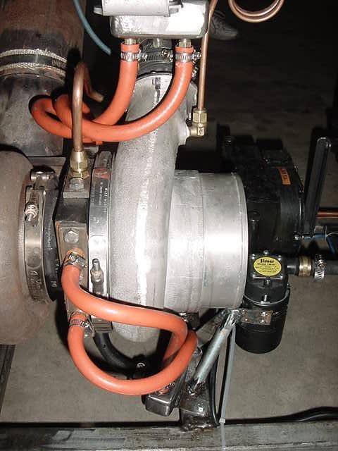
Today I finished the manifolds. I mounted the new water pump below the radiator. I mounted the manifolds so the inlet manifold was the lowest point in the cooling system. I mounted the outlet manifold below the top of the radiator so it would not be difficult to fill the cooling system. The turbo has 2 cooling passages with a small equalization passage between the passages. The initial setup was with an inlet and outlet on each passage. We then filled the cooling system with water and a water soluble lubricant to lubricate the water pump impeller. We started the turbine and let it run for 15 minutes. The water reached 101 degrees F. This was not good because it was not pulling enough heat from the turbine and would not allow for proper material expansion in the center section of the turbine. So we the switched the inlet hoses to one side and the outlet to the other side and allow the coolant to flow through the equalization passage. This would allow the coolant to remain in the turbine longer for more heat saturation. We then install a 1/2" ball valve on the outlet manifold before the radiator. This would allow us to control the water flow to regulate the coolant temperature. We went to start the turbine and when we turned the fuel on we heard an awful screech. I immediately turned of everything off at the instrument panel. We were tired and called it a day.
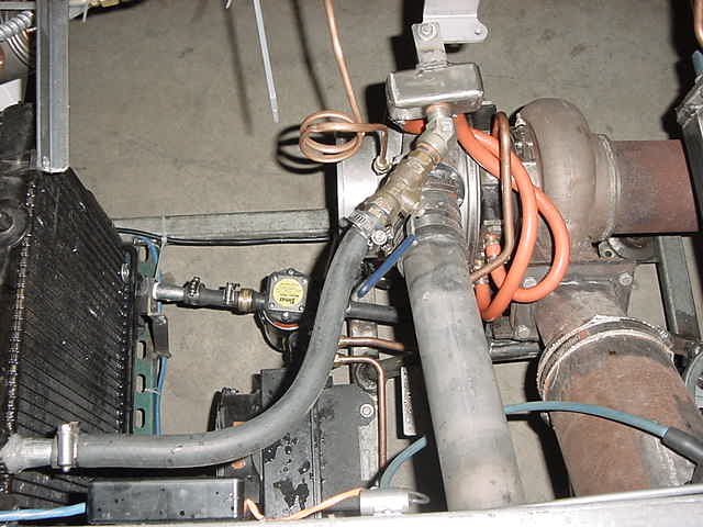
Turbine outlets for cooling water Water pump, inlet/outlet manifolds and hoses
I removed HT2 from the test stand and disassembled it. I found that the compressor wheel had caught some debris between the wheel and the housing. I tore the rest of the turbine down and inspected the turbine wheel, housing and bearings. Everything else looked great. So I cleaned up the scrapes in the compressor housing and replaced the compressor wheel. I then installed HT2 back into the test stand. I started HT2 again and it ran excellent. It ran for about 5 minutes and the coolant was at about 140 degrees F. I then closed the valve about 60% and the temperature came up to 200 degrees and stayed there. I was very pleased that I did not even have to turn the radiator fan on. The temperature can be controlled with the valve. I will figure out a bypass so I do not have to load the water pump unnecessarily. I will figure a way to maintain a constant temperature in the turbine and do it with a thermostat.
Radiator, water pump, manifolds, hoses Outlet manifold, ball valve, radiator and water pump overhead view
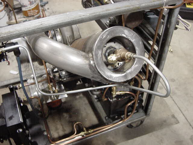
I work on installing the Banner D12SP6FPY sensor for the tachometer after work today. I installed the banner fiber optic lead in a 1/4" brake line tube. I crimped the end of the tube to hold the finished end of the lead to the tube. I then filled the tube with epoxy to permanently hold the sensor in the tube and help insulate the lead from heat soak after the turbine is shut down. I then drilled a 3/8" hole in the inducer of the compressor at an angle that placed the lead about 1/8" from the compressor wheel nut. I then welded a flange to the tube to fasten the assembly to the inducer. Next I painted half of the nut flat black and the other half gloss white. This turned out very nice and clean. Next I wired the sensor to the power source and started the turbine. I hooked the leads from the banner sensor to a frequency meter and got readings fluctuating between 80-90 hz to 0 hz no matter what the engine speed was. I figured I had transient voltage in the leads to the meter so I placed a 10k resistor across the meter leads and it worked perfectly. I can run the turbine at a set speed without the meter changing it reading. I ran the turbine to 78,000 RPM's. The boost was at 32 PSI, fuel pressure was only 100 PSI. This turbine will run much faster but 80,000 RPM is maximum speed for this turbine. At 60,000 RPM's the boost is at 17 PSI and the fuel pressure is 67 PSI.
I installed a water injection system today. The point of injection was between the combustor and the turbine inlet. I welded a 1/8" pipe nipple to the flame tube. I then took a 3/16" steel brake line and formed the end flat only leaving a small slit fir the water to exit. I used 12 volt dc diaphragm pump with an adjustable pressure switch to regulate the pressure of the water . I used a precision needle valve for regulating the amount of water introduced into the turbine with a pressure gauge on the pump side of the valve. I started the turbine and allowed a warm up period and then began the tests. First let me state that my expectations were that the water would hit the hot air from the combustor, flash into super heated steam and expand. This in turn would cause an increase in RPM's and cooler exhaust temperatures. The results were that no matter what RPM the turbine was running, there was no increase in engine speed. In fact, engine RPM always decreased with a drop in exhaust temperature of 40 to 110 degrees F. I do not understand the decrease in RPM. The only explanation I can think of is that I cooled the combustor gasses causing a decrease in RPM. The other explanation is that the steam caused friction on the turbine blades causing the reduced RPM's. I tried varying amounts of water with the more water the more the reduced engine speed. It is my belief that I am not introducing the water correctly and my original theory will hold true when corrected. I will continue with different arraignments in the future.
You can email me @ [email protected] Check back, I will update frequently
|