 |
 |
 |
 |
 |
 |
 |
 |
 |
 |
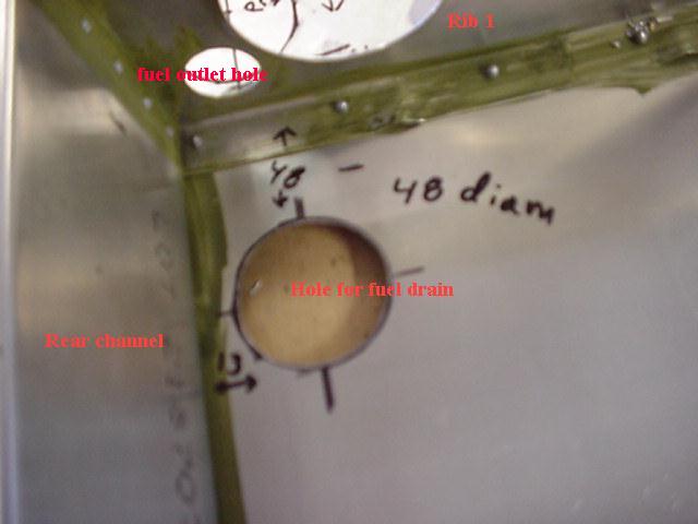
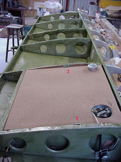
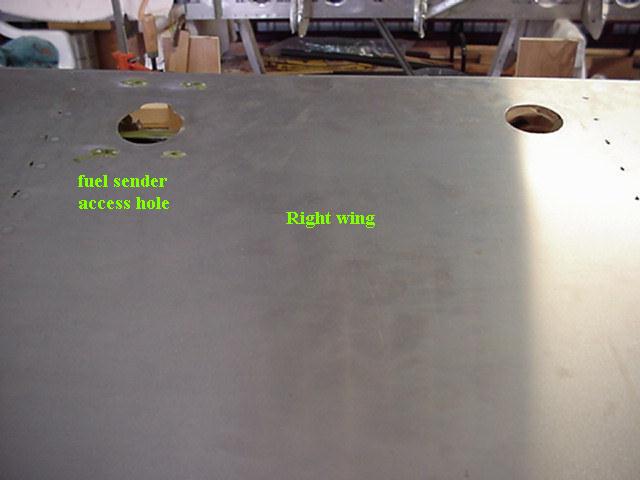
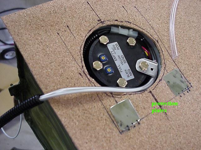
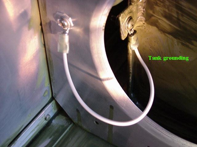
When I looked where the rear channel would put the tank I found it was against the spar and that the fuel outlet fitting hole would be partly in the lightening hole of rib 1. I didnt like this and got ZAC to send me new rear channels that were still taller than the tank, and when flush with the top and bottom of the ribs 1 and 2, I could cut the fuel outlet hole in rib 1 for the fuel outlet and the front of the tank would be about 20 mm from the spar cap. I put an access cover over the fuel sender and needed space for anchor nuts aft of the spar cap. (note: in the USA fuel quantity indicators are required for each tank) The anchor nuts for the back of the cover clear the tank as it is lower than the top skin. I put aluminum protection plates on the top of the cork at the screw locations, see pix. I also put an access hole inboard of rib 1 in the bottom skin under the fuel outlet fitting so I can get to it, if needed (pix shows where I later cut hole). The tank is held in place only by the cork lining and cork covered brackets, it is essentially wedged in place. I painted the aluminum with zinc chromate then used contact cement to hold the cork.
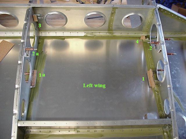
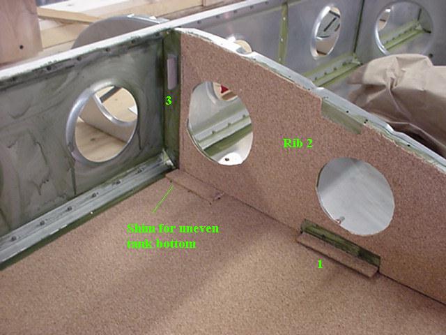
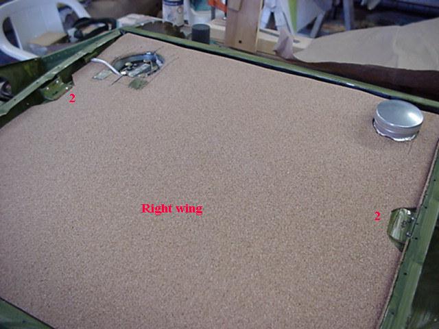
I didnt like the tank was only supported at the front and rear so I added "L" brackets (#1 in pix) midway, and level with where the tank rested on the front and back of the bottom skin. The bracket on rib 1 stands away from rib 1 with a hat shaped standoff. I lined the bottom, rib 2 and the rear channel with cork. The tank is jammed against the rear channel and rib 2. The standoffs on rib 1 are sized to force the tank against rib 2. Note the brackets that touch the tank are lined with cork. Use contact cement on the cork and "L". When you put on large pieces of cork, glue them down right after you cut them, as any humidity changes will change their size especially hole locations. All of the brackets are against a welded seam, which seem to be more rigid.
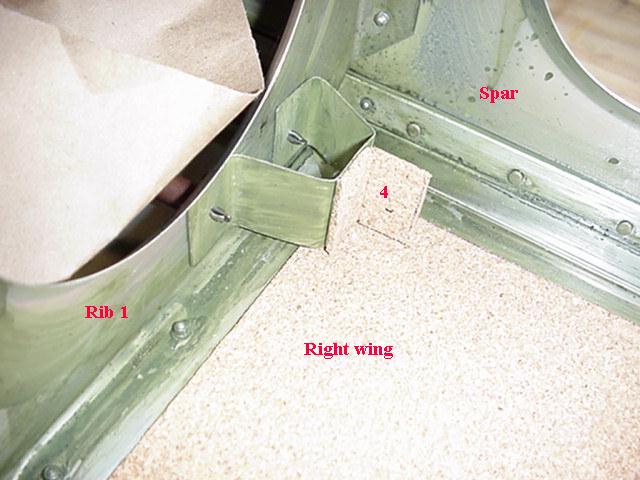
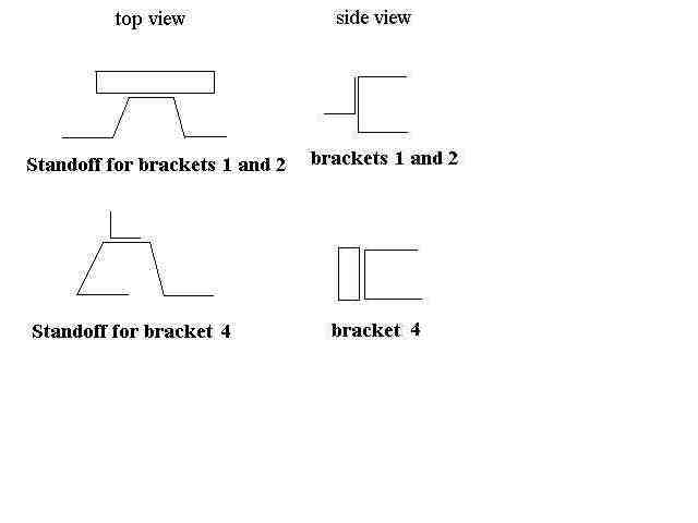
Brackets 1 and 1a support the bottom of the tank, brackets 2 and 2a hold the tank down, bracket 3 holds the tank aft and bracket 4 holds the tank aft and against rib 2. Brackets 1a, 2a and 3 are .025 "L" material. Brackets 1, 2 and 4 are .025 "L" supported by standoffs of .025. There is a drawing with the shapes of the standoffs. The standoffs should be under compression to hold the tank secure. One way to do this is to make the legs slightly longer than the required distance so they have to be spread to fit. Then squeeze the legs together to get the proper force when drilling the holes. Brackets 2 and 2a should exert a little downward force as well. Allow for thickness of cork.
Watch where rivets may touch tank. Usually the welds and flanges
on the tank provide plenty of clearance. Plan to rivet the brackets
2, 2a, 3 and 4 after the tank is in place.
|
|
|
|
|
|
|
|
|
|