WELCOME TO THE SITE OF M. PANDIAN
Last updated on 27 April 2005
|
Network synchronisation
|
|
NETWORK SYNCHRONIZATIONThis page has been developed with the help of Sri. V.Gnansekaran, SDE,STR,Salem. WHY NETWORK SYNCHRONIZATION IS
REQUIRED? To transport bits across a network or multiple networks, as well as national boundaries, without losing bits, network synchronization is required. Technical: Minimize data loss Increase the speed Political: Comply with international standards Overall: Deliver superior quality telecom service
WHAT IS SYNCHRONIZATION? · Synchronization: Keeping all digital equipments in a communication network operating at the same average rate is called as synchronization and it must exist at three levels. 1.Bit 2.Time slot 3.Frame · Bit synchronization: Transmit and Receive ends of the connection should be operated at the same clock rate, so that bits are not misread. · Time Slot Synchronization: Time slot synchronization aligns the transmitter and receiver so that time slots can be identified for retrieval of data. A network clock located at the source node controls the rate at which bits, frames and time slots are transmitted from the node. A second network clock is located at the receiving node, controls the rate at which the information is read. The objective of network timing is to keep the source and receive clocks in step, so that the receiving node can properly interpret the digital signals.
SLIP: Differences in timing at nodes within a network will cause the receiving node to
This is referred to as a slip. In ‘E1’ communications buffers are used to control slips. Data is written into buffer and is read from the buffer at different rates. Receive equipments will drop an entire frame and this is called controlled slip. The basic objective of network synchronization is to limit the occurrence of controlled slip. Slips can occur for two basic reasons. 1. The lack of frequency synchronization among the clocks. 2. Phase movement (such as jitter and wander) between the source and receiver clocks. How does Slip affect communication signals? · Voice calls - Crackling Noise · Fax - Incorrectly transmitted pages; Missing characters · Data - Low throughputs · Video - Picture freezes briefly; Black patches · Encrypted data - Retransmission of encrypted code · Wireless - Call dropping and delayed call handover
SYNCHRONIZATION DONE SO
FAR: PCMs (E1 Streams) working on PDH / SDH systems are taken as reference for the synchronization of the Transmission system or Switching equipments. The synchronization plan has to be reviewed for the following reasons: · Unlike PDH, the SDH systems introduce unusually higher jitter on the PCM tributaries. · The PCMs working on SDH are unsuitable for sending clock signals from one point to another.
SYNCHRONIZATION METHODS: DOT / BSNL have adopted Master-Slave / Centralized (Hierarchical Sound-receiver) architecture. Every major station, in a National SDH Ring and Sub regional ring is provided with a SSU. Reference clock for synchronizing other Transmission system and Switching Equipment has to be derived from the SSU. SSU: Synchronization Supply Unit, which minimizes the excess accumulated jitter and wander in the network due to cascading of SDH systems. SSU provides multiple 2 MHz signals for distribution. SSUs are not clock sources by themselves but they clean a clock signal coming from a master source. · In a SDH system, Two sync input and Two sync output ports are available. This sync outputs can be used for synchronizing Switching equipments and other SDH systems in that station. · Other than SDH system synchronization, STM MUX / ADM MUX are to be synchronized from the incoming STM (Synchronized Transport Module). · PDH systems have sync facility. · Stations, where SDH systems are not available, E1 streams can be use for sync purpose. · If the station is having SDH system, the clock from the sync out port should only be used as reference clock for the Switching Equipments.To take more than one Clock output, clock drivers may be used.
CONCLUSION: When can we call our Network Synchronized? ·
All ADMs are receiving clock from some SSU in the
vicinity. ·
All the STM MUX are synchronized from the incoming
STM. ·
All the Switches are synchronized from the sync
out port of the SDH system. ·
A synchronous network is one where the clock used
by any ADM can be traced back to the PRC (Primary Clock); VSNL Clock
Mumbai. Note: A sample Synchronization architecture is attached. 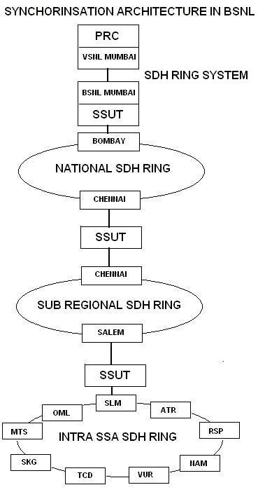
|
|
|
|
Page viewed best in 800 x 600 pixels resolution