The next thing we do is turn the PVC ring into a "clamp", by cutting a
length-wise slit into it. I chucked it into a vise and used a small backsaw.
Once this is done, I worked the slit over with a file and sand papper to obtain an even 1/16 inch wide gap.
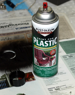
I sanded all the rough edges and marks off and painted it black with paint specifically designed for plasic.
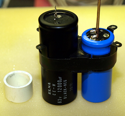
Notice that the replacement cap is a "snap-in" type. There are no solder lugs.
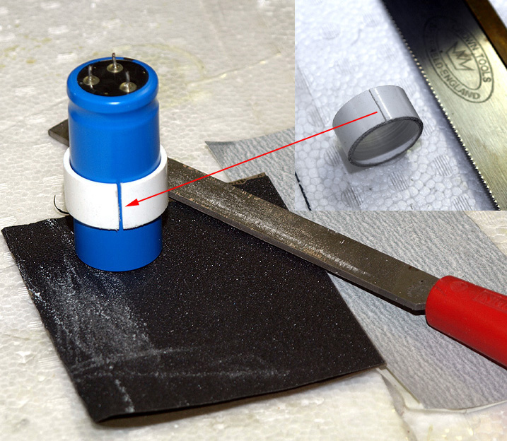
I used a 30mm length of 1 inch PVC pipe. It is 33mm in diameter.
The real problem is getting a solder lug that would reach through the 30MM length of the spacer, and provide a rigid solder joints for the PCB.
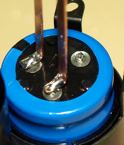
With some careful measuring, to determined the needed offset to position the new leads in the correct position, I put a bend in the lead to form a "foot".
I slipped the 16ga snap-in post into the hole at the "toe of the foot", and slid the new leads down to the base of the capacitor, and bent the post over onto the foot. This provided a mechanical retainer. I then soldered the connections.
It is quite rigid.
It is not real pretty, but everything below the clamps sits below the frame and can not be seen, so the looks of things here do not really matter. As long as it is functional.
Now, do three more of these...
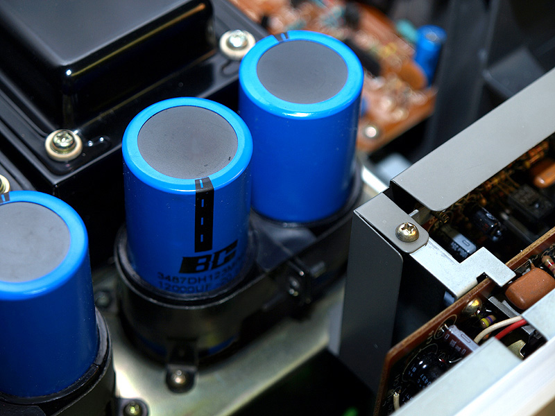
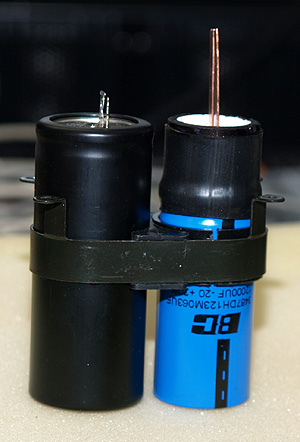
The finished cap assemblies slipped nicely into place and the new caps look pretty spiffy....