 |
|
|
|
|
|
|
|
|
|
|
|
|
|
|
|
|
|
|
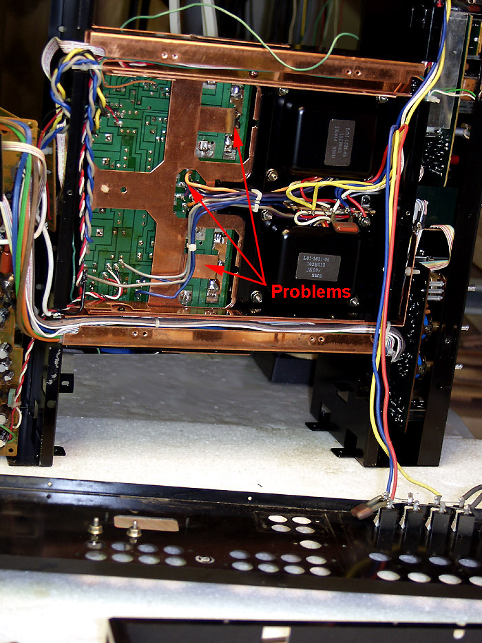
This is the first KA-907 I have worked on. While stripping this down I found a few road blocks.
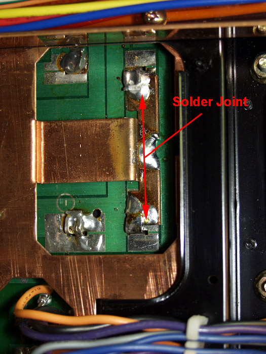
First, the large supply capacitors are soldered to the power supply board, which is soldered to the copper chassis. The solder joint is massive.
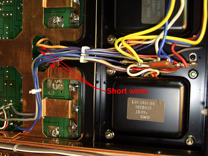
Second, the power supply leads to the main power supply board have very little "extra" length. |
|
|
|
 |
|
|
|
The solder joint runs the full length of the copper ground strap. You can't tell from the pictrue, but under the copper strap is a solid bead of solder, which runs from end to end. I did not want to attempt to remove that much solder. The copper frame will act as a big heat sink, which will increase greatly the amount of heat needed to loosen the solder. There is a big risk of damaging the board doing this.
|
|
|
|
 |
|
|
|
|
|
 |
|
|
|
There was not enough free wire on the transformer leads to allow for rewapping the wires. Each time a wire is unwarpped from a post, you lose the length of wire which was wrapped around the post. This is generally about 1.5 - 2 inches. You will need at least this much "free" wire to strip and rewrap. Kenwood usually leave generous amounts of wire in their units for this. hummmm.... someone been in this unit before? or is this a cost cutting thing? |
|
|
|
 |
|
|
|
I decided that a complete strip-down was too risky. The risk of causing un-repairable damage was too high. I decided to restore the amp in sections. This included new caps, washing all surfaces, grooming the components on the boards, and then voltage checks after assembly.
1. First the center section of the amp (power supply boards, tansformers, and center
section of the chassis.
2. Frontend (tone controls and front chassis section)
3. Backend (inputs, back panel, back side of chassis)
4. Output sections (output tansistors, heat sinks)
5. Face plate, cover, bottom plate, knobs |
|
|
|
Page Three -> |
|