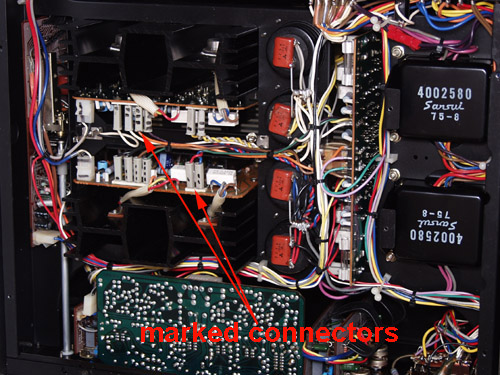
I set the amp on its side (transformer side down) and loosen all the wires from the wiring retainers on the bottom side of the frame. I clip the plastice ties arond the power supply and board that bind the wires together. The wires need to hang loose and be free of the frame... really, you can't get the PCB out of the frame without doing this!!! Then I loosen the capacitor bracket cinch screws so that the caps will slide down. Next I remove the metal brackets from the power supply PCB. Some of the screws in the back side are hard to get too. To make this easier I remove the screws that fasten the back panel to the frame. This allows the panel to swing back an inch or so, and it will give more room for the screwdriver.
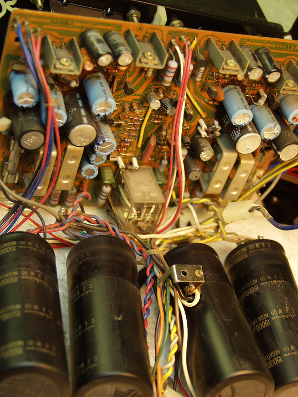
The Capacitors and power supply PCB will slide out through the bottom as one unit. Take your time and move the caps and PCB a little at a time.