Poor Man's SLV
A PVC-based St. Louis Vertical designed by KB0SPQ, Mark Arvidson
Why another version of the incredibly popular St. Louis Vertical (SLV)? Like so many other things I've done, the answer is, "because I can!" Actually, the idea sprung from planning for my summer vacation. My XYL and I were thinking of going to a beach, and I thought, "Gosh, maybe I should take along a radio." Although I wasn't entirely sure what this beach looked like, I was fairly certain there wouldn't be large trees perfectly positioned for a dipole. A vertical is the easiest answer. The SLV is a very attractive answer.
The SLV, while beautiful, has a couple drawbacks for me:
![]() I don't have $40 to spend on it (CHEAP for such a great antenna)
I don't have $40 to spend on it (CHEAP for such a great antenna)
![]() I don't have time to wait for the SD-20 or Black Widow
I don't have time to wait for the SD-20 or Black Widow
![]() I don't have a tuner
I don't have a tuner
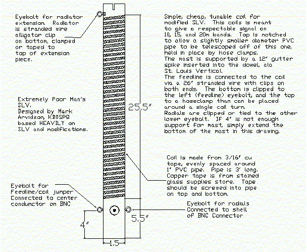
So, with that in mind, I now submit my latest antenna design:

A couple more words may be necessary to explain the antenna fully. Like I said, it's based on the SLV, so it is a base loaded vertical. Electrically, the coil section is probably the weakest section due to the copper tape. If it were wound of solid wire instead, and had a brass rod to choose tap points, it would simply be the neato-keen W6MMA SLV. Right now the idea is to attach a length of stranded between the feedpoint and the coil tap. I plan to connect the stranded wire to a thin hose clamp, but that may change, as the hose clamp will probably tap the coil too widely (more than one turn, all the way around). One solution I may use is to tape all but a thin (1/2" wide) grove along length of the coil. This would also provide mechanical and weather security to the rather weak glue on the back of the copper foil tape.
Another option for tapping the coil is to use small brass screws sunk into the coil through the copper tape. This is nice because you can tune up the coil and put screws in for particular frequencies, but requires considerably more initial setup time. It might be easier in the field, though.
The coil that I sketched out above is 40 turns on a 1.5" mast, which, if my math is correct, comes out to about 31.5 feet. Add to that a single eight-foot radiator from the top, and you can have an electrical length appropriate for quite a range. For 10 meters, tap near the top of the coil. For 40 meters, tap near the bottom. Depending on the length of the radiator you can easily move the coverage up or down.
Other modifications, such as using 3 five-foot sections, and topping the whole thing off with a whip would extend this system to 40 and even 80 meters, perhaps, but that's a bit down the road for me right now.
In order to ensure the mast stays upright in light to moderate wind, the dowel may have to be allowed to go into the bottom section considerably more. As a result, the BNC-Eyebolt setup may have to be moved up to 10 - 13 inches. This moves the entire feedpoint and antenna up, which actually may be an advantage. It certainly seems to help the SLV.
As you can see, it's not rocket science. I haven't actually built this antenna, yet, so I don't know how it performs. I have just been sitting here at work, and thought I'd sketch out my ideas. Anyway, I think I have some ideas about pros and cons for it.
|
|
Fairly lightweight. With three 3-foot pieces of PVC, and a dowel of wood, a single person will be able to carry it easily. |
|
It's heavier than the original SLV, with its super-light, super-strong fiberglass fishing rod. |
|
|
Tunable, simply by moving the feedpoint on the coil. |
|
Low power, as the Copper tape can't handle much. |
Like I said, I haven't built this yet, but we'll see if I can get it built by field day (one week from today), assuming I can come up with PVC money.
Oh, I also made a drawing of a sturdy workbench. Oolala! How exciting.
![]()