Type-R rear swaybar installation instructions
Disclaimer - Please read.
These installation instructions are intended for following cars:
- Acura Integra ('94-'01)
- Honda Civic ('92-'95)
- Honda Del Sol ('93-'97)
Here are the Acura parts that will be need:
1.) 52300-ST7-Z01 rear swaybar ($63.95)
2.) 52315-ST7-Z01 swaybar bushing ($4.08) (2 needed)
3.) 52308-SS0-000 bushing bracket ($5.66) (2 needed)
4.) 52316-ST7-Z00 endlink bushing ($1.62) (2 needed)
5.) 52312-SE0-000 endlink bushing collar ($1.81) (2 needed) � this part can be reused from the stock swaybar
6.) 90175-ST7-Z00 bolt (8x35) ($2.26) (2 needed)
7.) 94050-08080 flange nut (8mm) ($0.17) (2 needed)
Note: for Honda Civics ('92-'95) and Honda Del Sols ('93-'97) without a stock rear swaybar, you will need these additional parts:
8.) 52360-SH3-G31 lower contral arm (left) (1 needed)
9.) 52350-SH3-G31 lower control arm (right) (1 needed)
10.) 52303-ST7-Z00 endlink (2 needed)
11.) 90120-SB0-003 10x42 bolt (2 needed) - this bolt is for connecting the endlink to the LCA
12.) 95701-08018-08 8x18 bolt (2 needed) - this bolt is for the top mounting point
Note: all prices are from
Sunnyside Acura (prices current as of 10/22/2005)
Here are the miscellaneous parts that will be need:
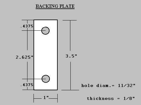
1.) 1/8" thick x 1.0" wide x 3.5'' long piece of plated steel (2 required).
*** INCLUDED IN MOUNTING KIT ***
2.) 1/2" (H) x 5/8" (OD) x 5/16" (ID) aluminum or steel spacer (2 required). *** INCLUDED IN MOUNTING KIT ***
3.) washers (inside diameter(ID) = 3/8") (outside diameter(OD) = 1") (2 required). *** INCLUDED IN MOUNTING KIT ***
*** MOUNTING KIT IS NOW AVAILABLE FOR PURCHASE ***
(please visit
www.geocities.com/bretq/mounting_kit.html for further information)
Note: Please see Figure 1 and Figure 2 to see the items listed above.
Here are the tools that will be needed: 12mm wrench, 12mm socket, 10mm socket, socket wrench, hammer, drill, 5/16" or 3/8" drill bit, chisel (optional).
Here are the steps for installing the Type-R swaybar:
- Jack up the back of car and support it with jack stands.
- Remove bolts (one each side) that attach the rear swaybar to the left and right endlinks.
- Remove bolts (two each side) that attach the swaybar bushing bracket to the swaybar mounting bracket.
- Remove bolts (two each side) that attach the swaybar mounting bracket to the suspension cross member frame.
- Remove bolts (one each side) from ABS sensor bracket (see Figure 3). Remove the spot welded nut from the inside of suspension cross member frame. This is the nut that attaches the ABS sensor bracket to the suspension subframe. The nut can be removed by using a chisel and hammer or by unthreading the bolt half way and hitting the bolt head with a hammer.
- Using a drill and a 5/16" or 3/8" drill bit, enlarge the ABS sensor wire bracket hole to accept the new bolt (8x35) (see Figure 4).
- Cut two pieces of 1/8 inch (thick) by 1.0 inch (wide) steel to the same length as the new swaybar bushing bracket (3.5 inches). Using a 3/8" drill bit, drill holes in the two steel pieces to match the holes in the new bushing bracket (see Figure 5). The new plates are used as backing plates since the GS-R does not have a flat mounting surface on the suspension subframe such as the Type-R.
*** OR BUY MOUNTING KIT *** (see Figure 6)
Insert new endlink bushing and endlink bushing collar into each end of the Type-R swaybar.
Attach Type-R swaybar to the stock end links using bolts removed in step #2. Do not torque bolts, this will be done in a later step. Note: please notice direction of bend in the swaybar (see Figure 7).
Place Type-R swaybar bushing over the swaybar. Place swaybar bushing bracket over bushing (see Figure 7).
Place fabricated backing plate on back of bushing bracket. Attach the top of the bushing bracket to the top hole vacated by the stock swaybar mounting bracket. Use one of the bolts that was removed in step #4.
A spacer of approx. 1/2 inch (see Figure 6) will be needed between the backing plate and the suspension subframe. Attach the bottom of the bushing bracket through the enlarged hole in step #6 using the new bolt (8x35 - this bolt is approx. 1/2 inch longer than the bolt that was used in step #10). Use the washer and flange nut on the backside of the subframe (inside chassis) to attach the bushing bracket to the bottom hole. Note: Loctite may be used on bolt threads to prevent them from coming loose.
Torque the bushing bracket bolts to the manufacture's specifications (16 lb-ft) (see Figure 7 and Figure 8).
Lower car and torque the endlink bolts to the manufacture's specifications (16 lb-ft) (see Figure 7 and Figure 8).
|
Figure 1

|
Figure 2

|
|
Figure 3

|
Figure 4

|
|
Figure 5
|
Figure 6

|
|
Figure 7

|
Figure 8

|
Click
here to download these instructions in Acrobat Reader format (.PDF)