
MOTOR EXPERIMENT
How to Make a Simple ELECTRIC Motor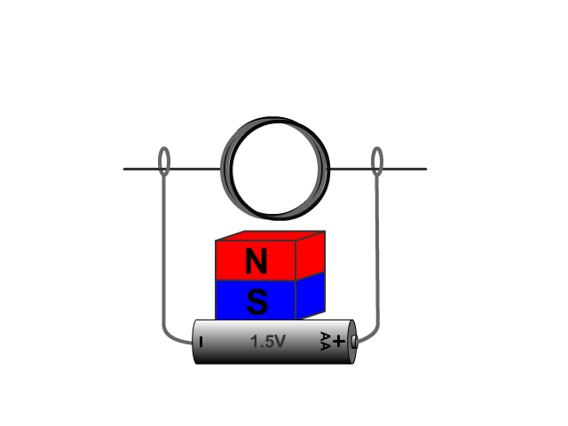
Energy comes in many forms. Electric energy can be converted into useful work, or mechanical energy, by machines called electric motors. Electric motors work due to electromagnetic interactions: the interaction of current (the flow of electrons) and a magnetic field.
Materials
- AA battery
- Insulated Magnetic wire
- Metal plate holder
- Electrical tape
- Side cutter/fliers
- Small circular magnet

Procedure
Starting in the center of the wire, wrap the wire tightly and neatly around the pipe 5 times.
Remove turned coil into the pipe and centered secure.
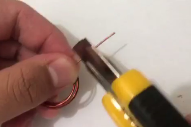
Wrap each loose end of the wire around the coil a 2 times to hold it together, then point the wires away from the loop
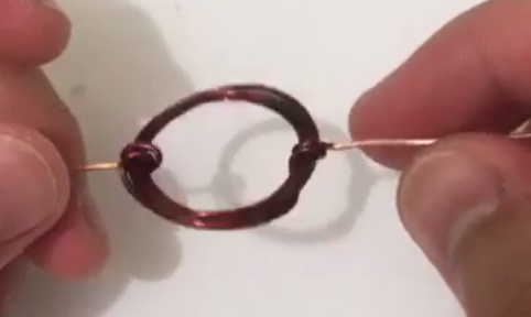
Remove the isolator coil in each side of the end
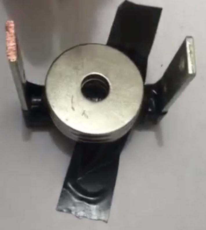
Use electrical tape to secure the metal plate holder upright next to the terminals of each battery so that the side of each needle touches one terminal of the battery.Your coil should be hanging above the battery.
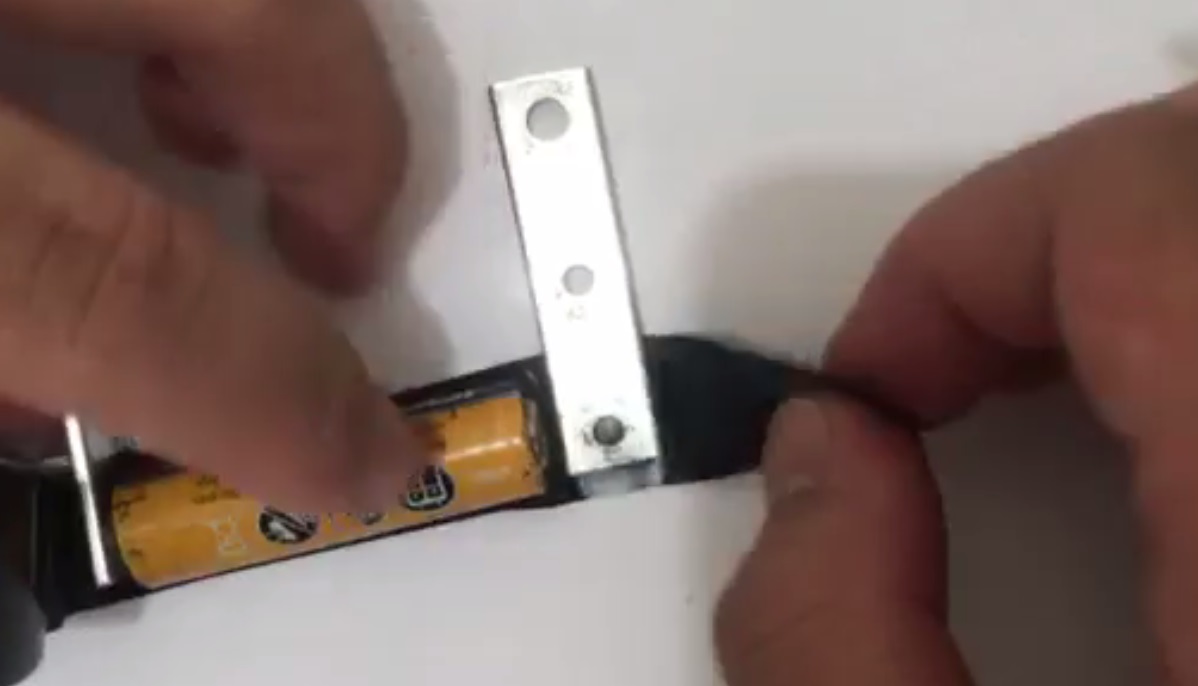
Lay the AA battery with the metal plate holder on a flat surface.and secure with electrical tape on the ground
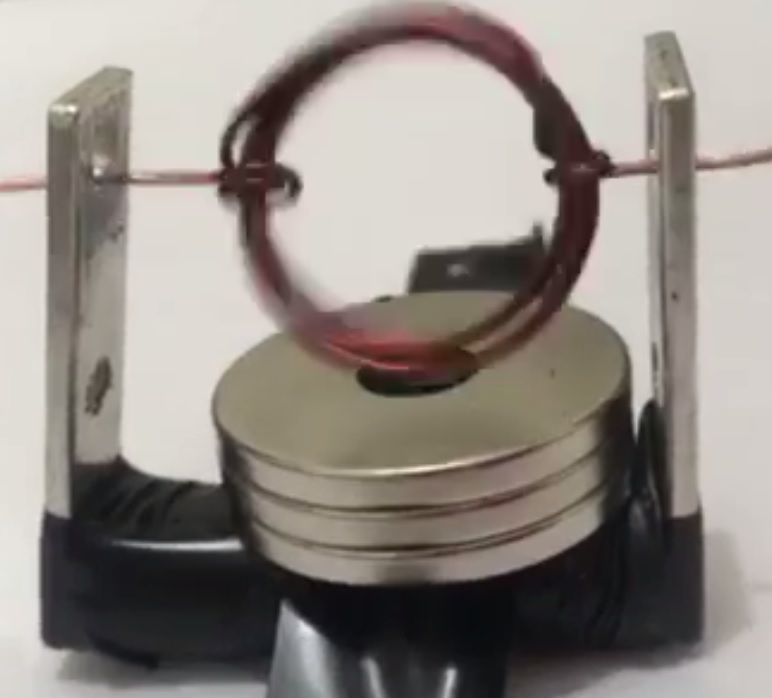
Place the magnet to the battery so that it is centered underneath the coil.
Give your coil a spin.
How to Make a Simple HOMOPOLAR Motor
The first homopolar motor was demonstrated by Michael Faraday in 1821.
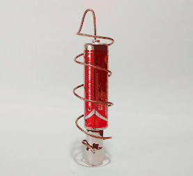
To make a simple motor that doubles as a work of art you will need three things
– a battery, magnet, and wire-
Energy from the battery travels in one direction (DC- direct current) from one end of the battery, to the other end. Copper wire, which conducts electricity, is made into a shape that connects the two ends of the battery, creating a continuous flow of electricity. The current travels through the copper wire back to the battery to complete the circuit.
The magnets in this experiment also have a positive end and a negative end creating a magnetic force that moves up towards the battery. This electromagnetic opposing force causes an outward motion, forcing the wire to spin in a circular motion. Here is a picture from MAGCRAFT illustrating the different forces.
Materials
- AA battery
- Insulated Magnetic wire
- Side cutter/fliers
- Small circular magnet

Procedure
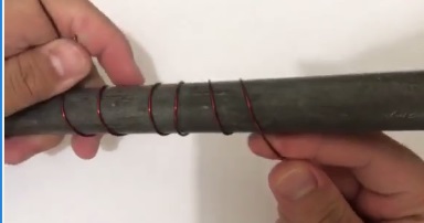
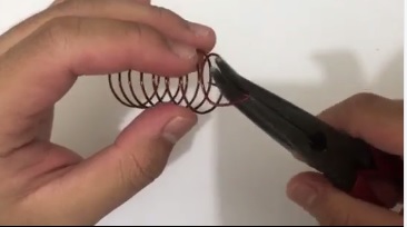
Take your copper wire and fold it in half and squeeze the bend together with your pliers,turn around the pipe 10 times.
Remove turned coil into the pipe
Remove the isr coil in each side of the end
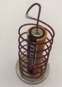
Place the negative side of the AA battery on top of a couple magnets. If you place a larger magnet on the bottom and stick with with double sided tape to the counter, this will help prevent the battery from falling over. Another trick that we found to be useful is to use double sided tape to attach two washers to the positive side of the battery, this will help the wire stay on.
Results
The motor will continue to spin when pushed in the right direction. The motor will not spin when the initial push is in the opposite direction.
Why?
The metal plate and wire created a closed loop circuit that can carry current. Current flows from the negative terminal of the battery, through the circuit, and to the positive terminal of the battery. Current in a closed loop also creates its own magnetic field, which you can determine by the “Right Hand Rule.” Making a “thumbs up” sign with your right hand, the thumb points in the direction of the current, and the curve of the fingers show which way the magnetic field is oriented.
In our case, current travels through the coil you created, which is called the armature of the motor. This current induces a magnetic field in the coil, which helps explain why the coil spins.
Magnets have two poles, north and south. North-south interactions stick together, and north-north and south-south interactions repel each other. Because the magnetic field created by the current in the wire is not perpendicular to the magnet taped to the battery, at least some part of the wire’s magnetic field will repel and cause the coil to continue to spin.
So why did we need to remove the insulation from only one side of each wire? We need a way to periodically break the circuit so that it pulses on and off in time with the rotation of the coil. Otherwise, the copper coil’s magnetic field would align with the magnet’s magnetic field and stop moving because both fields would attract each other. The way we set up our engine makes it so that whenever current is moving through the coil (giving it a magnetic field), the coil is in a good position to be repelled by the stationary magnet’s magnetic field. Whenever the coil isn’t being actively repelled (during those split second intervals where the circuit is switched off), momentum carries it around until it’s in the right position to complete the circuit, induce a new magnetic field, and be repelled by the stationary magnet again.
Once moving, the coil can continue to spin until the battery is dead. The reason that the magnet only spins in one direction is because spinning in the wrong direction will not cause the magnetic fields to repel each other, but attract.

WATCH VIDEO TUTORIAL