Home Profile Junkbot Projects  Materials Gallery

STD LOCK SYSTEM


STD Lock System Using Arduino:

In this project of we will learn How to design (STD)Smart Touch Door Lock System Using Arduino & Touch Sensor TTP223. Door Lock System using Arduino & TTP223 Capacitive Touch Sensor Switch is a simple project for switching circuit, i.e switching the servo motor on/off with the help of simple touch. The door can be locked or unlocked just by simply touching. We are using Touch Sensor TTP223 as a switch and LCD to display the status of door lock and LED to indicate on/off status as well. The application area of this project is home and office where a simple touch can open and close the door. Interfacing touch sensor TTP223 with Arduino acts as a switch for unlocking the door.


Components Required


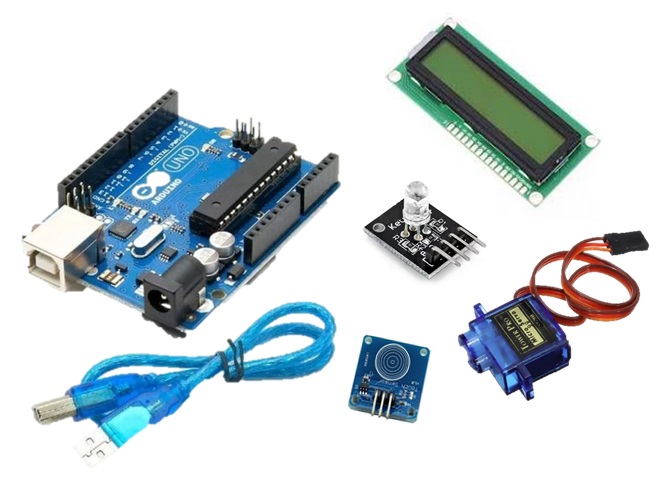
1.      Arduino Uno Board

2.      TTP223 Capacitive Touch Sensor

3.      16X2 LCD Display

4.       SG90 Servo Motor

5.       RGB Arduino Board

6.      Connecting Wires


TOUCH SENSOR  

Introduction:

capacitive touch sensor module based on the dedicated TTP223 touch sensor IC. The module provides a single integrated touch sensing area of 11 x 10.5mm with a sensor range of ~5mm. An on-board LED will give a visual indication of when the sensor is triggered. When triggered the module’s output will switch from its idle low state to high (default operation). Solder jumpers allow for reconfiguring its mode of operation to be either active low or toggle output.

Internal Structure:

TTP223 is 1 Key Touch pad detector IC, and it is suitable to detect capacitive element variations. It consumes very low power and the operating voltage is only between 2.0V~5.5V. The response time max about 60mS at fast mode, 220mS at low power mode @VDD=3V. Sensitivity can adjust by the capacitance(0~50pF) outside.

Working Mechanism of TTP223 Capacitive Touch Sensor

Capacitive screens do not use the pressure of your finger to create a change in the flow of electricity. Instead, they work with anything that holds an electrical charge – including human skin. When a finger hits the screen a tiny electrical charge is transferred to the finger to complete the circuit, creating a voltage drop on that point of the screen. The software processes the location of this voltage drop and orders the ensuing action.


Circuit Diagram & Connections

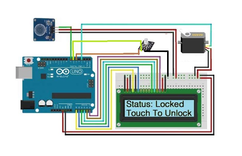
1.Connect the signal pin of TTP223 Touch Sensor to Arduino Digital Pin 7.
2.Connect servo motor signal pin to Arduino Digital Pin 3.
3.Connect the LED to Arduino Digital Pin 5 via a 330-ohm resistor.
4.Connect the LCD to analog pin A0, A1, A2, A3, A4, A5 of Arduino as shown in the figure. 


Practical Working of the Project: 

After the Code Uploaded the, the LCD will display 

1.Touch Based 

2.Door Lock System 


The Servo Motor will reset to the original position. 

If the Touch Sensor is Touched, the LCD will display 2 Lines 

1.Status: Unlocked 

2. Touch to Lock 


Similarly, Servo Motor will rotate by 180 degrees, and LED will glow. 

If the Touch Sensor is Touched again, the LCD will display 2 Lines 

1. Status: Locked 

2. Touch to Unlock 


Similarly, Servo Motor will rotate reversely by 180 degrees a and LED will get off. 


Source Code/Programs: 

NO VIDEO TUTORIAL

Using ultrasonic sound wave to be tested on an oscilloscope

What is Oscilloscope?

An oscilloscope is a machine that shows the wave shape of an electrical signal. When connected to a ultrasonic module they can show the wave signal.


The Arduino ultrasonic module includes transmitters, a receiver and control circuit. This distance sensor works by sending out an ultrasonic wave from the trigger terminal and detecting whether there is a pulse signal back through the echo. If there is a returning pulse signal, it is measured, and the length of time the pulse remains at a peak corresponds to the distance an object is from the sensor.


The longer the returning pulse is, the further the object is away. A short pulse of at least 10 micro sec is supplied to the trigger input to start the ranging, and the module sends out an 8 cycle burst of ultrasound at 40kilohurts, and the echo is raised. 


Here is how to calibrate an Oscilloscope:

With the use of Probe
put the ground then the test calibration and setup the settings.


Oscilloscopes principally measure voltage and time. Measuring another physical property such as temperature, pressure, flow, velocity, or displacement on an oscilloscope requires use of a transducer or sensor to convert the measured quantity into voltage. Using the oscilloscope's function you can scale the input voltages into units that match the transducer's input. 


Procedure

The 5V DC supply was connected to the VCC pin on the sensor.

The function output was connected to the Trig pin.

All the grounds were connected together

Chanel2 of the oscilloscope was connected to measure the input pulse (Trig).

Chanel4 of the oscilloscope was connected to the Echo pin to measure the returning pulse, if any.

Without any object positioned in front of the sensor, the following was obtained on the screen of the oscilloscope:

The function output was set to produce a low frequency pulse.

The distance was measured, and the waveforms displayed on the oscilloscope were recorded. The waveforms displayed were used to calculate the actual distance the sensor measured from the object.

An object was then positioned in front of the sensor:

And the oscilloscope displayed the following. Here the peak of the returning signal was of a duration of roughly 1.5milli second, the distance measured with the calculated distance of approximately 25cm

The object was then moved closer to and further from the sensor. One such position

The angle of the object to the sensor was also varied to test the sensor’s ability in detecting objects that aren’t straight in front of it.


Here the peak of the returning signal was of a duration of roughly 0.333milli second, and thereby measured a distance of approximately 5.5cm when calculated, which is close to the distance.

The angle of the object to the sensor was also varied to test the sensor’s ability in detecting objects that aren’t straight in front of it. One such position

The waveform displayed on CH4 of the oscilloscope indicates that the object was approximately 25cm from the sensor, thereby showing that the sensor can quite accurately detect the distance it is from an object that is an acute angle. This maximum angle at which the sensor detected the object during testing was approximately 20°.


One negative about this sensor is that it’s blind for the first 2cm, but more importantly, careful mounting must be adhered to, as if it’s positioned too high it won’t detect other robots and if it’s positioned too far back on the robot, it will detect itself and presume it’s an opposition robot


STD Lock System