
SKYBUSTERS ONE CHIP IRD LOGGER
MODIFICATION
First
of all this mod has been tested and works a treat and secondly
Skybusters
will not be held responsible for any damage so take your time!!!!
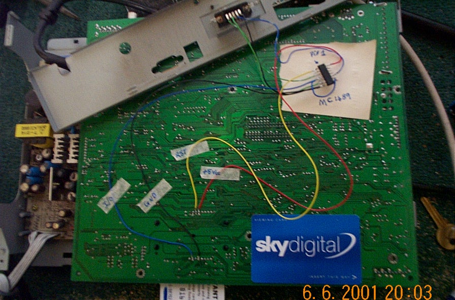
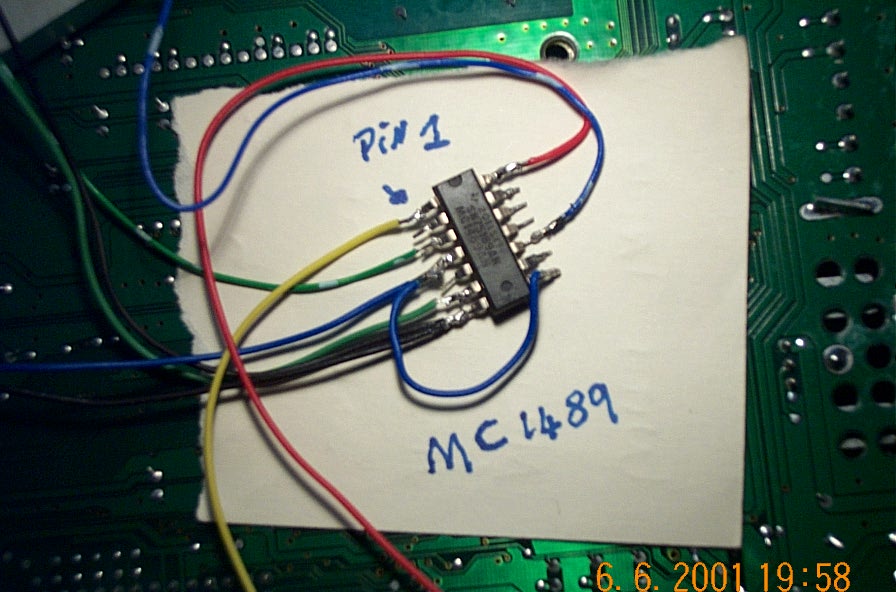
Once you have fitted all the wires to the chip its ready to be fitted in the box,
There are only 3 wires soldered to the main board smart card slot. See (DAIG.2)
So�.
Remove all the screws holding the outer case and remove the main board circuit board, this makes it lot easier to work on.
Turn the main board upside down with the card slot opening facing you.
Connect the BLUE wire from PIN 4 of the mc1489 to the smart card slot I/O pin
Connect one of the BLACK wires from PIN 7 of the MC1489 to the GND pin of the smart card slot
Connect the YELLOW wire from PIN 1 of
the MC1489 to the Reset pin of the smart card slot
DO NOT CONNECT THE RED WIRE AS DISPLAYED IN (DIAG
2)
For the RED wire you have to find an
alternative +5V supply in the main board otherwise the IRD will detect the
voltage drain on the card slot and shut the box down! This can easly be achieved
using the multi meter but leave this connection till last so once the ird is put
back together a connection point can easly found.
(DIAG.2) 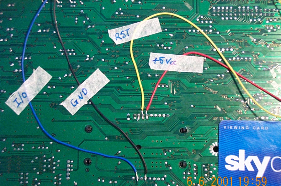

Stage 3 (and final stage)
Ok�
All that�s left to do is add the new db9 female
connector to the back of the ird casing, this was easily achieved by cutting a
small hole in the back plate to house the new db9 connector, once the connector
is fitted the remaining wires can be connected as follows: (DIAG.3)
Take the remaining BLACK wire
connected to PIN 7 of the MC1489 and connect to PIN 5 of the Db9
Connect the GREEN & WHITE wire connected to
PIN 3 of the MC1489 and connect to PIN 1 of the DB9
Connect the GREEN wire from PIN 6 of the MC1489 to
PIN 2 of the DB9
Connect the BLUE & WHITE wire from PIN 10 of
the MC1489 to PIN 3 of the DB9
(DIAG.3) (Not the best of Diags
but im no photographer!)
just check all the connections are correct and put
the ird back together again, find a suitable connection point for the RED wire
and BINGO!
OH!! And don�t forget to tape the chip up in pvc tape to stop any shorting out!