 |
|
|
|
|
|
|
|
|
|
|
|
|
|
|
|
|
|
|
|
|
|
|
|
|
|
| Type-5 Panel and Chassis Fabrication |
|
|
Back
Home
Next |
|
|
|
|
|
 |
|
|
|
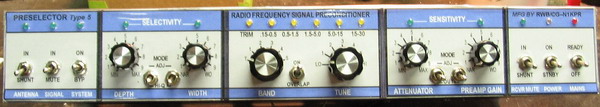
The finished front panel, printed and laminated, with controls, knobs and LEDs mounted. I used smooth laminate material, so there is some light reflection in the photos. |
|
|
|
 |
|
|
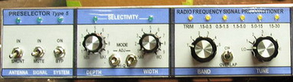
| Closeup of the left side. |
|
|
|
 |
|
|
|
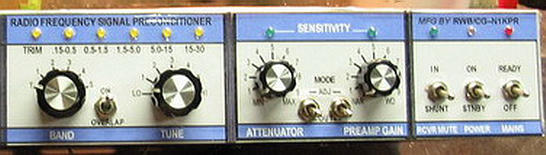
Closeup of the right side. |
|
|
 |
|
|
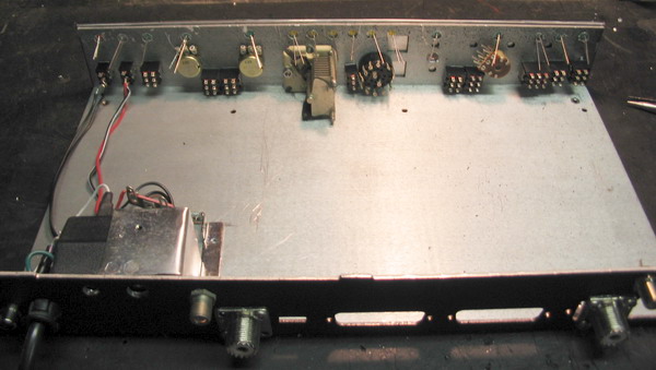
View of the inside with the controls mounted, input/output connectors (UHF and F-type), and power supply.
Note the DB connector holes ... this was some sort of computer box.
There is plenty of room for the preamp and any other (experimental) circuitry that may come along. Since the PS will deliver about 300 mA, there is also an added power port to run any other 12 V accessories. |
|
|
|
|
 |
|
|
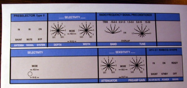
This is the panel graphic printed on peel & stick label stock. Nothing fancy; all you need is some sort of graphic program, a lot of time, and a ton of patience. Once printed, you can apply tin laminating plastic. Take your time designing - you'll have to live with your creation for a long time! |
|
|
|
|
|
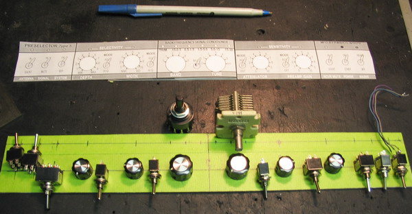
On the bench is an early B&W printout of the above graphic. Note that the panel is longer than 11 inches, so the print had to be taped together.
Below it is the aluminum panel, covered with masking tape. This is a check to be sure all the controls fit. The panel is then marked and drilled. Then apply the printed decal and cut out the paper holes through the aluminum panel holes with a hobby knife. Pretty easy so far ... huh? |
|
|
|
|
|
|
 |
|
|
|
|
|

|
|
|
|
Next page in a week or so ... |
|
|
|
|
|
|
20 Aug 2006 |
|
|
|
|
|
|
|
|