- The ratio of inductance to inductive reactance is proportional. That is, for a given frequency, as inductance goes up, reactance goes up.
- In filter circuits, there are two forms of Q (efficiency): Component Q, and filter Q.
- Component Q is the quality of the device: Reactance/Resistance, Z/R.
- Filter Q is the efficiency of the filter loop: ratio of the loop impedance to the filter impedance.
- Series tuned resonant circuits are at minimum impedance at resonance.
- The efficiency of series tuned filters increases as the circuit (loop) impedance decreases.
- Parallel tuned resonant circuits are at maximum impedance at resonance.
- The efficiency of parallel tuned filters increases as the circuit (loop) impedance increases.
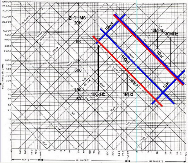
Let's assume a filter design for a single center frequency of 1 MHz. Follow the 1 MHz line vertically. Note that with the 10-365pf capacitor (red), inductors of from 100 uH to 2 mH will resonate at the design frequency. Note the highest impedance is when the cap is at the lowest value. Also note that at the capacitor's greatest value, the filter's impedance is only about 500 Ohms and at its lowest value the filter impedance is about 15,000 Ohms!
Now look at the smaller capacitor (blue) and see that the impedance range of the filter is 1,500 to 15,000 Ohms. It becomes quite obvious that using a variable tuning cap with a value range that is restricted to about 10:1 is the better choice for a high-Q filter circuit. It is also apparent that the lowest value that the variable cap is capable of, should be selected based upon the band of frequencies of interest and the availability of suitable high-Q inductors of complementary value.
Please read: Preselector Design and Theory
