The performance of the amplifier/attenuator circuit may function better if that portion of the circuit were at 50 ohms instead of 12 ohms.
Modification:
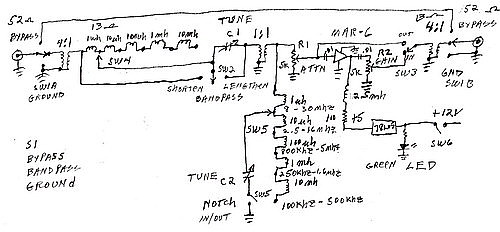
Remove the 4:1 output transformer and insert it directly after the 1:1 interstage transformer which feeds the "null" circuitry. Everything from the Attenuator pot to the output jack will then be at 50 ohms.
Analysis:
This combination circuit is still experimental and subject to some final design adjustments. The above modification depends largely on the type of device selected for the amplifier stage. Generally speaking, RF amplifiers perform well in the 30 to 300 ohm range, but this is not a hard and fast rule.
Further design notes shall be posted here as they are confirmed.
--B. Betts
* All wiring should be as short and direct as possible (see Richard's panel layout).
* Ground all DC power connections to the metalic chassis. Do not use bypass capacitors from the power mains to ground as noise filters.
* DC Isolation: Depending on your total system conditions and various other equipment, which is interconnected in your station, an electrical ground may, or may not increase noise - you may try it both ways.
* Ground-bonding (Electrical/Lightning Safety) is very important for minimal noise (elimination of ground loops). Your station's Earth ground system should be electrically bonded to 1. the input of the preselector, 2. the preselector output and/or the input of your receiver, 3. the antenna selector switch (if used) and, 4. of course, the antenna(s) coax shield(s).
* Redundant AC electrical (power mains) grounds may cause ground loops (your radio is probably connected to the mains ground through the line cord). In practical experimentation, I have found a well-regulated wall wart or table top power supply, with the DC outputs isolated from electrical ground, to work well.
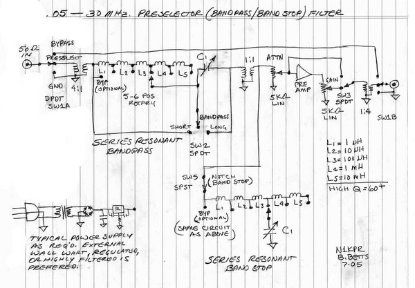
* Capacitors C1 and C2 should be mounted with nylon standoffs to keep the roter isolated from ground (shaft extensions may be required).
Many of the items are from Mouser, http://www.mouser.com/
The enclosure is from Digikey, http://www.digikey.com/
The vernier dial and variable capacitors are from Ocean State Electronics, http://www.oselectronics.com/ose_p101.htm, http://www.oselectronics.com/ose_p96.htm
Some parts are from my own stock.
(Also try HOSFELT Electronics, ALL Electronics, Marlin P. Jones, and Jameco.--Bob)
