Go to Page 2: Grounding
* * * A Bad Rap? * * *
- End-Fed antennas are NOT balanced systems; but neither are verticals, ground planes, discones, windoms, zepps, Marconis, half-slopers, et al. Additionally, the low-impedance antenna port of your transmitter/receiver is not balanced.
- End-Fed antennas are noise magnets. Really? That's because most hams and SWL-ers don't bother to interface them properly.
- End-Fed antennas have wild impedance swings. So do all antennas, but not at the design frequency - there, at the design frequency, the terminal impedance is quite predictable.
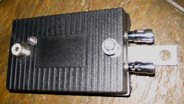
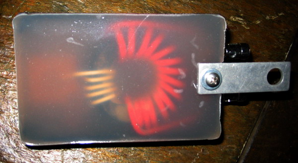
To make the best use of an End-Fed antenna, it should be fed with a transformer. Here are some photos of one of my 9:1 baluns. However, when using it with an End-Fed antenna it is wired as an "unun" transformer (unbalanced to unbalanced).
The raw End-Fed antenna will go through impedance swings as high as 5K Ohms, or more, at even multiples of its 1/4 wavelength design frequency. At every odd multiple it will be at a more civil impedance of between 36 and 90 Ohms. Using the transformer, the magnitude of the impedance swings is greately reduced. This is due, in part, to the ratio balancing of the transformer's turns (windings), and to a few complex reactance and other physics attributes that I won't try to cover here.
Additionally, the unun will eliminate (virtually) all "common mode" currents on the feedline. This is important for eliminating the pickup of local electrical noise from homes and power distribution lines. The coax, being connected to ground through a DC path will eliminate all but the differential currents ... pretty cool, huh?
Finally, since the antenna is connected directly to Earth ground through the secondary of the transformer, static buildup cannot occur - the antenna is a dead (DC) short to ground. This is important to sensitive, solid state radios. Without getting into "Lightening Safety" theory and practice, sufice it to say that not having a positively charged static generator sitting around waiting for a very large negatively charged cloud to pass over, is a good thing. There is still a lot of conjecture about this, but most 'lightning protection system' engineers agree: Having an Earth-neutral antenna over (near) your home is, in effect, like placing that area closer to ground. Well, maybe. Some "experts" disagree. In any case, as any physicist will tell you, there is NO absolute protection against a direct lightening strike, (even underground, in a cave!) but you can certainly take measures to NOT attract a strike ... and this is one of them!
1. a much flatter broadband impedance response,
2. a static elctricity-free antenna system (no buildup),
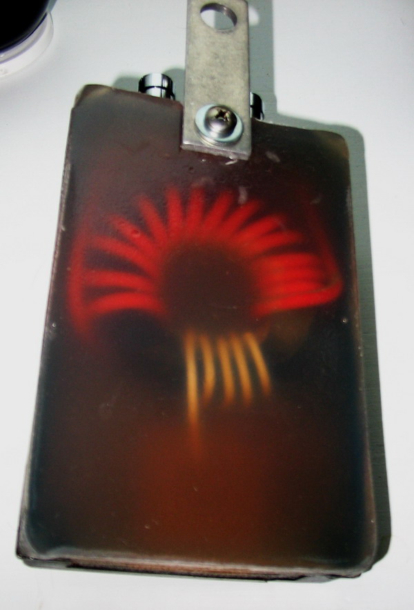
3. common mode noise immunity (if space wound as shown).
The impedance is the square of the turns ratio (Z=T^2). The antenna terminals are brass speaker terminals and the low impedance side is a standard SO-239. The grounds of the two windings have been isolated but, can be strapped together by the screw contacts (shown in the top photo). The entire assembly was potted with marine fiberglass. Note that I also added a hanger strap for convenience.
Properly designed and constructed torroid transformers are not lossey!!!
On the test bench with a 52 Ohm source and a 450 Ohm load the transformer shows a loss of no more than 0.6 dB with about 0.45 dB being average, and the low reading of 0.2 dB.
