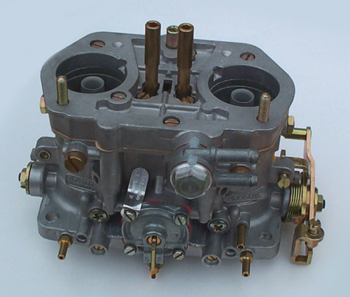
dellorto DRLA 36,40,45 & 48.
Diag Part Diag Part
No. No. Description Sizes/options
available No. No. Description
1 10527 DRLA36/40 Choke (Venturi) 26,28,30,31,
32,33,34,36 43 6581 Spindle nut lock washer
1 10758 DRLA45 Choke 32,34,36,38,39 44 7537 Spring washer
1 11486 DRLA48 Choke 38,39,40,41,42 45 7490 Spindle bearing
2 10078 DRLA 40 Auxiliary venturi No longer available 46 10353 Retaining clip
2 10527 DRLA45 Auiliary venturi No longer available 47 10135 Nut
2 11487 DRLA48 Auxiliary venturi No longer available 48 7413 Choke return spring
3 7484 Main jet 85,90,95,100,
102,105,108,110, 49 10252 Choke piston
3 110 to 190 in steps of 1, 190,192,195,198…
210-240 in 5's 50 10137 Choke actuator cam
4 7644 Idle jet 32-82 in 1's 51 7062 Choke cable bolt
5 10927 Pump jet 30,33,35,38,40,42,
45,48,50,55,60 52 10156 Return spring
6 3315 Starter jet 40-90 in 5`s 53 6850 Choke cable washer
7 9164 Main emulsion tube No's 1,2,3,4 54 10110 Drive link
8 7482 Starter emulsion tube No`s 1,2,3,4 55 6432 Choke cable nut
9 7485 Air corrector 80,90,100,110,115,
120,125,130,135 56 10231 Cover plate
9 140,142.5-202.5 in
2.5`s 205-250. 57 9174 Set screw
9 10304 Tall air corrector jet 160,170,175,180,
190,000 58 10140 Choke cable bolt
10 10305 Needle valve (metal) 150,170,200,225 59 7231 Choke washer
10 10375 Neddle valve turbo (viton) 150,170,200,225
cross drilled 60 10817 Choke lever
10 8649 Needle valve, viton tipped 250,270,300,350,
400 cross drilled 61 10311 Choke cover
11 10133 Throttle butterfly DRLA 36 62 5011 Lock washer
11 7481 Throttle butterfly DRLA 40 63 4957 Lock washer
11 8010 Throttle butterfly DRLA 45 64 10253 Screw
11 8563 Throttle butterfly DRLA 48 65 2906 Nut
12 10090 Float 66 10928 Pump jet holder
13 10097 Fuel banjo, return 11mm bolt Carb details required. 67 6426 Pump jet
holder fibre washer
13 12393 Fuel banjo, return 16mm bolt Carb details required. 68 10748 Pump jet
Filter/spring
14 10132 11mm banjo bolt Carb details required. 69 6173 O ring
14 12390 16mm banjo bolt Carb details required. 70 7571 O ring
15 10134 11 mm banjo seal 71 10138 Manometer fitting
15 7662 16mm banjo bolt seal 72 8678 O ring
16 10096 Fuel banjo, double 11mm bolt 73 9926 Air bleed screw
17 1419 Fuel Filter 74 9663 Pump diaphragm spring
18 10570 Banjo bolt seal 75 10182 Pump diaphragm
19 6430 Top cover screw 76 10256 Pump cover plate
20 4957 Lock washer 77 5011 Lock washer
21 10066 Top cover Carb details required. 78 6429 Screw
22 10092 Top cover gasket 79 10315 Lock nut
23 6288 Needle seat sealing washer 80 10340 Retaining washer
24 10154 Float hinge screw 81 10332 Spring
25 8498 Retaining clip 82 10331 Sleeve
26 10339 Float hinge screw 83 8260 Retaining washer
27 10738 Idle jet holder 84 9336 Spring
28 7540 Sealing O ring 85 10316 Pump rod
29 7542 Pump non- return valve 86 10686 Retaining clip
30 7513 Cap screw 87 9656 Mixture screw
31 10630 Top cover stud 88 10153 Pump rod clamp
32 7636 Pump jet weight 89 7667 Pump rod clamp screw
33 6415 Pump jet ball bearing 90 8857 Progression blanking cap
34 7540 O ring 91 9754 Screw
35 9754 Throttle stop screw 92 6423 Lock nut
36 7958 Spindle end cover 93 7507 Venturi grub screw
37 10230 Linkage drive arm 94 10790 Butterfly spindle
38 10142 Step washer 95 6416 Throttle butterfly screw
39 10184 Throttle lever 96 10157 Return spring
40 10158 Throttle return spring 97 10183 Throttle lever
41 10130 Washer 98 10229 Throttle lever
42 6423 Spindle nut 99 52534 Gasket set
1. FEATURES
Twin choke downdraft with 36-40-45 mm diameter barrels.
Interchangeable chokes from 28 to 38 mm.
Butterfly throttle valves.
Constant-level float chamber with double float.
Starting device with independent circuit.
Idle circuit with centrally placed jets and Venturis supplied from the main jets;
mixture adjustment screws with means for sealing them so as to make them tamper-proof.
Main circuit with centrally placed jets and emulsion tubes.
Accelerator pump with mechanically-operated diaphragm with single inlet valve
and two delivery valves upstream from the jets.
By-pass screw in each barrel to equalize the air flow to the throttle valves in
the idle position.
Special design for use on turbocharged engines with pressurized (blown)
carburettor.
2. OPERATION
2.1 - Fuel Supply
Fuel arrives at the fuel inlet (15) through the filter (16) and reaches the seat
(19) where the needle (20), anchored to the float (21), adjusts the flow of fuel
into the chamber thus ensuring a constant level of fuel. The float chamber is
vented through the hole (4). Any excess fuel sent by the pump to the carburettor
is returned to the fuel tank by the air corrector jet (17) of the fuel inlet
(18).
2.2 - Starting
When the starting throttle (7) is completely open, the fuel, metered by the jet
(11), passes into the emulsion tube (10) where it is mixed with the air coming
from the passage (3) and is then made to pass through passage (5). Through the
two holes (9), the mixture thus formed arrives in chamber (8) where it is
further mixed with air coming from passages (22). It is then distributed into
the two channels (12) which reach the main barrels (14) downstream from the
throttle valves (13). When the valve is partly open, i.e. when it is desirable
to have a leaner mixture, the fuel is further mixed with air coming from the
hole (6) which is connected with the valve chamber (1) which, in turn, is
connected to the atmosphere through hole (2). When the starting valve (7) is
closed the passage between the barrels and the starting device is also closed.
In addition, the separator (23) will close off the two barrels (14).
2.3 - Idling
The fuel which arrives from the float chamber (34) by way of the main jets (36)
reaches the idling key (33) through passage (35); it is here mixed with air
coming from the air corrector jet (25) and, through channels (24) and (27),
reaches the adjustment screw (32). Properly metered, it arrives in the main
barrels (14) downstream from the throttle valves (13). With the coupling (50)
connected to a vacuum meter it is possible to measure, through channel (51) and
the hole (49), the pressure in the barrels (14) with the throttle valve (13) in
the idling position and consequently to equalize the air flow by turning the
by-pass screw (29) which controls hole (30). The depression advance take-off is
made through the calibrated hole (31) which is connected with the coupling (28).
The screw (26) adjusts the opening of the throttles in the idling position.
2.4 - Progression
On first opening the throttle valve (13), that is, in passing from idle to top speed, the mixture will also reach the barrels (14) through the progression holes (48).
2.5 - Acceleration
When the throttle valves (13) are opened, the lever (46) fastened to the spindle
(47), pushes the pump lever (42) by means of the rod (45) and the spring (44).
The pump lever operates directly on the diaphragm (40) against the action of the
spring (39). The movement of the diaphragm causes fuel to be sent to the main
barrels (1 4) through the corresponding valves (38) and the throttle valves (13)
are closed, the diaphragm (40) returns to its original position under the action
of the spring (39) and it will once again draw fuel from the float chamber (34)
through the valve (41). The delivery of the pump can be adjusted by turning the
nut (43).
2.6 - Full Throttle Running
When the throttle valves (13) are fully open, the fuel arriving from the float
chamber (34) and calibrated by the jets (36) enters the wells (56) and is mixed
with the air metered by the air corrector jet (54). The mixture thus formed
passes through the centering inlet (53) where it is further mixed with the air
taken in through the main carburettor inlet, arrives in the Venturis (55) and,
subsequently, reaches the engine through the main barrels (14).
3. ADJUSTMENT
3.1 - Idling
Any idling speed adjustment may only be carried out if it is possible to use an
appropriate CO meter to measure engine emissions. Only under these conditions is
it possible to break the seals and subsequently to carry out the required
adjustments to obtain a correct idling speed. The bypass screws (c) on the
carburettor must be completely closed while the mixture adjustment screws must
be opened through 5 turns from their completely closed position. Any adjustment
must always be made with a hot engine and the throttle screws (a) turned until
the required rpm’s are reached. To equalize the airflow in the two barrels,
please consult the instructions “Carburettor Synchronisation and Idle
Adjustment”. Now proceed to obtain an engine operation which is as smooth as
possible by turning the mixture screws (b), while still keeping within the
prescribed values for engine emissions.
Bear
in mind that the percentage of CO is increased when the screw is turned up
whereas it is decreased when it is turned down. If a CO meter is not available
it is only possible to operate on the throttle adjustment screw (a) so as to
obtain the best idling speed.
3.2 - Accelerator Pump
The adjustment of the accelerator pump must be carried out by placing the
carburettor on the bracket with its gasket in place, connecting it up to the
fuel tank so that fuel is supplied properly. Put the two 10 cc graduated
measuring tubes under the support drain pipes so that all the fuel that is
pumped is collected. Open and close the throttle completely 20 times, with a few
seconds’ break in between, and check that the volume of fuel collected in the
two tubes is identical and corresponds to the specifications. Should this not be
the case, the delivery of the pump should be adjusted by turning the adjustment
nut on the pump control rod, bearing in mind that to increase the delivery of
the pump it will be necessary to turn the nut down, while to decrease it, the
nut will have to be turned up.
At this point repeat the checking operation until the exact adjustment is
reached.
3.3 - Float level
Check that the weight of the float corresponds to specification as shown on its
body. Check also that it is not damaged and that it rotates freely on its pins.
Hold the lid in the vertical position so that the float arm is in light contact
with the needle. In this position check that the two half-floats are at the
specified height in relation to the float chamber lid with the gasket fitted in
the normal position.
3.1 - Idling
Any idling speed adjustment may only be carried out if it is possible to use an
appropriate CO meter to measure engine emissions. Only under these conditions is
it possible to break the seals and subsequently to carry out the required
adjustments to obtain a correct idling speed. The bypass screws (c) on the
carburettor must be completely closed while the mixture adjustment screws must
be opened through 5 turns from their completely closed position. Any adjustment
must always be made with a hot engine and the throttle screws (a) turned until
the required rpm’s are reached. To equalize the airflow in the two barrels,
please consult the instructions “Carburettor Synchronisation and Idle Adjustment”.
Now proceed to obtain an engine operation which is as smooth as possible by
turning the mixture screws (b), while still keeping within the prescribed values
for engine emissions. Bear in mind that the percentage of CO is increased when
the screw is turned up whereas it is decreased when it is turned down. If a CO
meter is not available it is only possible to operate on the throttle adjustment
screw (a) so as to obtain the best idling speed.
3.2 - Accelerator Pump
The adjustment of the accelerator pump must be carried out by placing the
carburettor on the bracket with its gasket in place, connecting it up to the
fuel tank so that fuel is supplied properly. Put the two 10 cc graduated
measuring tubes under the support drain pipes so that all the fuel that is
pumped is collected. Open and close the throttle completely 20 times, with a few
seconds’ break in between, and check that the volume of fuel collected in the
two tubes is identical and corresponds to the specifications. Should this not be
the case, the delivery of the pump should be adjusted by turning the adjustment
nut on the pump control rod, bearing in mind that to increase the delivery of
the pump it will be necessary to turn the nut down, while to decrease it, the
nut will have to be turned up.
At this point repeat the checking operation until the exact adjustment is
reached.
3.3 - Float level
Check that the weight of the float corresponds to specification as shown on its
body. Check also that it is not damaged and that it rotates freely on its pins.
Hold the lid in the vertical position so that the float arm is in light contact
with the needle. In this position check that the two half-floats are at the
specified height in relation to the float chamber lid with the gasket fitted in
the normal position.