STEAM TURBINE
![]()
Mode of operation of the steam turbine
Since it is a steam jet and no more a water jet who meets the turbine now, the laws of thermodynamics are to be observed now. The modern steam turbine is an action turbine (no reaction turbine), i.e. the steam jet meets from a being certain nozzle the freely turning impeller. There's a high pressure in front of the turbine, while behind it a low pressure is maintained, so there's a pressure gradient: Steam shoots through the turbine to the rear end. It delivers kinetic energy to the impeller and cools down
thereby the pressure sinks.
Steam is produced in a steam boiler, which is heated in power stations by the burn of coal or gas or by atomic energy. Steam doesn't escape then, but after the passage through the turbine it is condensed in a
condenser and then pushed back into the steam boiler again by a pump. This has the advantage that for example in nuclear power stations work- and cooling water are clearly separated.
Multi-level steam turbines
In modern steam turbines not only one impeller is propelled, but several being in a series. Between them idlers are situated, which don't turn. The gas changes its direction passing an idler, in order to perform optimally work again in the next impeller. Turbines with several impellers are called multi-level. The principle was developed 1883 by Parsons. As you know, with the cooling gas expands. Therefore it is to be paid attention when building steam turbines to a further problem: With the number of passed impellers also the volume increases, which leads to a larger diameter of the impellers. Because of that, multi-level turbines are always conical.
Coupling of several turbines
In power stations today, different types of turbines are used in a series, e.g. one high pressure -, two medium- and four low pressure turbines. This coupling leads to an excellent efficiency (over 40%), which is even better than the efficiency of large diesel engines. This characteristic and the relatively favorable production make the steam turbine
competition less in power stations. Coupled with a generator and fired by an atomic reactor, they produce enormously much electric current. The strongest steam turbines achieve today performances of more than 1000 megawatts.
Turbine components
1. Cylinder:
It is carefully designed so that thermal changes shall produce symmetrical movement and thereby reduce to a minimum possibility of distortion.
2. Rotor:
It is machined from a solid forging of alloy steel with thrust bearing.
3. Blading:
It is consists of a moving blades and a stationary blades where the steam flow comes from turbine chest and goes through a stationary blades to direct the steam to the moving blades and rotates the moving blades.
4. Balance piston:
The inlet of the HP rotor is machined to form two stages balance piston which is designed to overbalance the thrust on the Blading and the extraction dummy and thus produce a thrust toward the inlet of the machine under all operation condition.
5. Journal bearing:
It has two journal bearings and lubricated by oil to avoid friction.
6. Thrust bearing:
It is a leveling type where the load is distributed equally among the several shoes and it is supported on leveling plate 15,16.
7. Turning gear:
It is used to rotate the shaft at low speed (3 RPM) while turbine is shut down.
8. Rotor Gland:
It is located at both the governor end & at the generator end, with seal strips to minimize steam leakage in order to keep the system under vacuum, labyrinth type.
9. Breakable Diaphragm:
It is a mounted on the turbine exhaust cylinder cover for purpose of
providing automatic emergency relief should the internal pressure rise beyond the
maximum safe value for designed cylinder (>105 bar). It is more likely a relief valve.
10. Coupling:
It is a rigid type, it is machined integrally with the turbine rotor the other is
fitted on the generator rotor. The two hands are bolted together rigidly by the bolts 75.
Inlet nozzle
These nozzles are located directly after the steam chest and it takes the spherical shape. The use of the inlet nozzles is to rotate the turbine where
the steam expands and changes from pressure to velocity.
fig.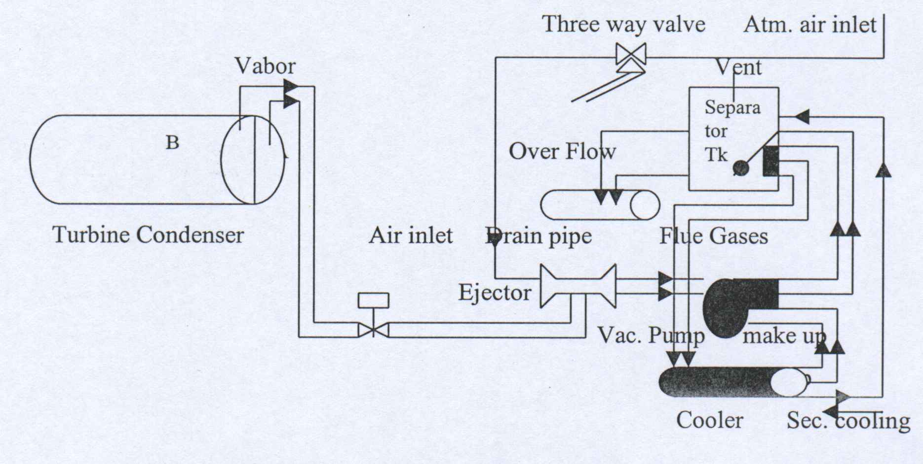
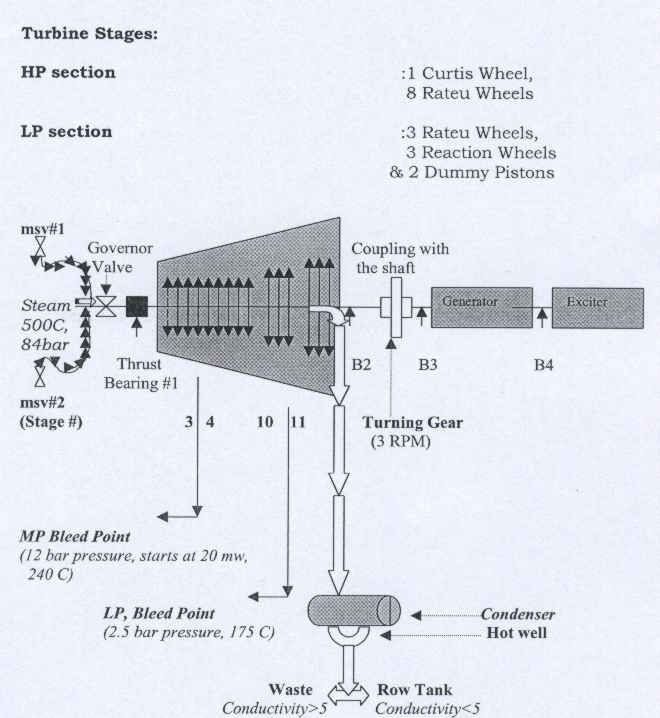
Condensate Conductivity
The condensed steam that is accumulated in the condenser hot well and it has two ways to go depending on the conductivity factor. Either to waste if the conductivity is more than five p.s, or to the Row Tank when the conductivity is less than five p.s.
MP Extraction:
The MP extraction is located in the turbine internal casing between blade Sand 4.The MP steam has a specification of 12 bar pressure, and 220 c temperature. The use of this steam is for the vacuum system in the desalination units. A part of the medium steam goes to the following:
Steam converter unit.
Heating the deaerator (1,2).
Turbine gland Steam.
The steam that is going to the vacuum system ofMSF units goes through a control valve which is located outside the turbine to manage the steam flow. MP steam pressure and temperature that is coming from turbine is controlled by PIC in order to reduce the pressure at least from 15 to 12 bar and TIC to reduce the temperature to 220 C by a spray water.
LP Extraction:
The LP steam is located between stages 10 and 11. It has a specification of 2.5 bar pressure, and 175 c temperature. The use of this steam is mainly for heating purposes. MSF units heating medium in the brine heater in order to heat the brine heater water to the desired top temperature (TBT). The rest of the low-pressure steam goes to the condenser after completing its job and rotating the turbine.
The LP steam goes through the extraction governor valve inside the turbine which controls the outgoing steam flow to the LP header. The size of the blades gets bigger and bigger towards the condenser side because of the high pressure and that leads to a high in the specific volume.
Gland Steam system:
The purpose of this steam is to seal the turbine and minimize the steam leakage in the turbine chest and HP, MP extraction. As well as to prevent any air of getting in to the condenser which might cause a vacuum lose, decreases in the condensation and steam moves in reverse direction.
In the turbine start up we take the gland steam from the 12 bar header and reduce the pressure to approximately .2 mbar and the temperature to 180 and after the starting we take the steam directly from the turbine. The pressure of the gland system is set between 0.1 ~ 0.2 mbar and is
controlled by two valves which are:
1. Leak valve: If the Pressure increase more than 0.2 mbar then the leak valve will open and send the additional steam to the condenser. Otherwise steam will get out side of the turbine through either the MP or LP gland steam. This is considered as a power lost since it reduces the turbine efficiency.
2. Control valve: if the decreases less than 0.1 mbar, then the control valve will open and adjust the pressure. In case if the control calve did not open then the steam will get out of the MP ext. and at the same time the air will get in the LP ext. And that will cause a vacuum lost in the condenser and the turbine will shut down due to a DUE POINT.
The gland steam temperature is also controlled and set at 180 C. In case if the temperature increases or decreases then this will effect the seal point expansion, and then the relative expansion, (which is the space between the moving blades and the stationary blades which is + /-0.03 mm), and this will cause the thrust bearing trip.
Turbine Main Valves
Main Stop valves:
There are two stop valves are located on the 85 bar line inlet to the turbine (to the right and left). Through the main stop valve the 85 bar steam gets into the turbine. It is either in open or close position but in the start up sequence it changes to be a control valve until the system stabilizes and then it get back to normal as a shutoff valve. It is working by the hydraulic system and the pressure is approximately 9 to 10 bars.
Governor valve:
After the steam passes through the main stop valves, it gets to the governor valve and then to the steam chest. The function of this valve is to control the steam inlet to the turbine and through that to control the load. The valve opening percentage depends on the control signals by using the high pressure of oil from the hydraulic system, which is around 9 to 10 bar.
Extraction Governor valve:
The extraction governor valve is found at the LP extraction of the turbine, it is located inside the turbine between stages 10 and 11. The purpose of this valve is to extract the LP steam (2.5 bar, 140 C) from the turbine low-pressure section. The valve opening percentage depends on the control signals by using the high pressure of oil from the hydraulic system that is around 9 to 10 bar.
1 Ton steam = 6.3 ton distillate
Vacuum system
In the turbine hall we have three vacuum pumps which are used to make an evacuation inside the condenser (-. 98 Barg) and usually one is in service. The function of the vacuum pump is to make vacuum medium in the condenser in order to maintain the stability in the system and vacuum the exhaust steam from the turbine and at the same time to increase the efficiency of the system.
fig2.13
Air extraction pumps
In the steam turbine there are two air extraction pumps right next to the vacuum pumps. The job of these pumps is to extract the air and the bubbles from the seawater in the tube side (water box). Also it is used to evacuate the seawater inlet to condensate and allow the seawater to cover the condenser tubes as much as possible in order to increase the heat exchange rate which will increase the efficiency of the turbine itself.
Condensate pumps
The function of the two-condensate pumps is to pump the condensate water that came from the turbine cycle to row tank in case of a low conductivity (less than five micron). Other wise the condensed water will be pumped to waste if the conductivity reaches over 5 usec.
Lube oil system:
The lubrication oil system is supplied by the main oil pump and supplies to the lubrication system passes through the oil cooler and hence to the main bearing, thrust bearing, and turning Gear. There are four different types of pumps, which are available in the Lube oil system which are in which are:
1. Auxiliary oil pump: AC, 9 bar, and through a control unit the pressure reduces to 2 bar for lubrication. The use of this pump is to supply oil to the ejectors and high pressure oil system and also to void any friction in the bearing side specially the thrust bearing.
2. Emergency oil pump: DC, 1.0 ~ 1.8 bar. This pump is provided to supply oil to the bearings, and turning gear, in case of a Block shutdown by using batteries (DC supply) as a power supply.
3. Turning oil pump: AC, 1.0-1.8 bar, the use of this pump is to supply oil to the bearings and turning gear during the shut down in order to avoid any distortion before the shaft rests.
*Turning the shaft is 3-Rotates per minute.
4. Main oil driven pump: Rotate by the shaft, it works at the speed of 2910 RPM in a place of the auxiliary oil pump while the turbine is in service. The main oil driven pump pressure is between 9.3 ~ 11.3 Bar which is quite enough for lubrication and also for the hydraulic system.
Hydraulic system:
The hydraulic system is part of the Lube oil system. It is used for controlling the steam flow by controlling the extraction governor valve, governor valve and the main s top valves (10 bar).
When the turbine speed is less than 2910 RPM the auxiliary oil pump is used for the hydraulic system to control the MSV, GV, and EGV. But when the turbine speed reaches 2910 then the supply will come from the main oil driven pump and it will be used to control the MSV, GV, and EGV. After some time when the turbine is put in service the controlling of the MSV changes to be
open/ close position only.
![]()
![]()