FLOW Nature, Characteristics and Utilization of Crude oil
Just as in any other industry, profit is one of the main considerations in the petroleum industry. Along with many other factors, the profits are governed by the demand for the product. Whether or not the required quantity and quality of the products can be obtained economically from the raw material available is an important consideration. Crude oil, being the raw material for the petroleum industry. the study of the crude oil is important.
Crude oil is composed almost entirely of infinite combination of the two elements carbon and hydrogen. Therefore, all the oil products like gasoline, kerosene or fuel oil are made up of hydrocarbons. Actually the^hydrocarbon mixtures in crude are so complex that only relatively few of the hydrocarbons can be isolated. Many of the thousands of hydrocarbons, particularly in the higher boiling ranges defy identification even by the most modern analytical methods. Hydrocarbons in crude, as previously mentioned, usually belong to the paraffin series (Cn Hin+l), the aromatic series (Cn Hn^6) and the naphthenic series (Cn H2 n).
A small percentage of the combination of hydrocarbons with elements like oxygen, sulphur and nitrogen is also present in the crude oil. The oxygen is found in the form of naphthenic acids. Nitrogen is most often found in the naphthenic base oils and is generally supposed to be in the form of basic compounds. Sulphur may be found as free sulphur, hydrogen sulphide or as organic compounds such as thiophenes, mercaptans, alkyi sulphates or sulphides. Sulphur compounds are particularly bad because they are foul smelling and corrosive.
Types of Crude Oil
Crude oil is a mixture of hydrocarbons with some sulphur, nitrogen and oxygen compounds. Crudes with very little sulphur are called sweet crudes, and those with high sulphur content of the order of one percent or more are called sour crudes, A crude with high percentage of naphtha or and other low boiling range distillates will have a high API gravity or low density and are known as light crudes. Those with a small percentage of naphthas and a large percentage of high boiling range hydrocarbons will have a low API or high density and therefore, are known as heavy crude.
Crudes are also broadly classified into four categories—Paraffin base, mixed base, naphthene base and aromatic base. Paraffin base crudes contain principally paraffins in the lighter fractions and alkyi naphthenes in the heavier fractions. The kerosene, diesel fuel and lubricants obtained from this crude are usually high and of best quality. Naphthene base crude oils have a high percent of naphthenes with very little of wax. Gasoline obtained from naphthenic crudes are normally good and the lube oil fractions respond well to the extraction process. Aromatic base crude oil contain a high percentage of the lower aromatic hydrocarbons. The asphaltic base crude oils are of high specific gravity and yield poor quality gasoline. The diesel and kerosene obtained from the asphaltic crudes are of poor quality. The fuel oil and asphalt fractions obtained from these crudes are usually high. These classifications along with the other properties like sweet and sour, heavy and light is used for evaluating the crude. Complete data of a crude oil, however, is determined by an assay which consists of a true boiling point distillation and correlation of properties such as octane number, vapour pressure, aniline point, sulphur etc.
As mentioned previously, crudes from different geographical locations vary considerably in the physical properties and composition. They may be heavy and viscous or may be light and less viscous.
The usual products obtained from a refinery are gas, naphthas, kerosene, diesel oil, lubrication oils and fuel oils. The maximum percentage yield of the product of a certain boiling range from a given crude by distillation is fixed by the amount of the material present in the crude.
In general, the refining processes consist basically of physical operations such as fractionation, extraction, and chemical operations like platforming, hydrogen treating.
Crude Oil Assay
The classification of crudes as paraffin base, naphthene base, aromatic base does not provide sufficient information for a refiner to determine the type of crude to be used for refining. The complex nature of crude oil makes it difficult to evaluate crude oil by determining the individual components. Therefore, a crude oil assay procedure has been developed and is accepted as the most suitable technique for evaluation of crude oil. A crude oil assay essentially consists of a complete inspection of the oil, a true boiling point distillation to obtain cuts that can be correlated with refinery operations, a quality evaluation of the cuts and a series of correlations to interpret the data.
The petroleum inspection carried out on a crude oil provides general information on the character of the crude and indicate in many instances when special processing is required. The typical inspections
are tabulated below.
1. Gravity
2. Sulphur
3. Pour point
4. R.V.P.
5. B. S & W
6. Salt content
7. Distillation
8. H 2 S content
9. Viscosity SSU at 60°F
10. Viscosity SSU at 80°F
11. Viscosity SSU at 100°F
API gravity and viscosity inspections provide a broad indication of the gasoline, kerosene and diesel oil yields. High viscosity may indicate high asphalt content. Viscosity and pour point also provide information on crude oil pumping characteristics. Salt content of crude indicates whether a desalter is necessary or not.
True boiling point distillations have wide application in determining the yields of several fractions that may be obtained from crude. The true boiling point distillation is carried out at high reflux rates to obtain effective fractionation. In this distillation crude is split into narrow increments of increasing boiling point. Blends of appropriate increments are recombined to provide fractions which are tested to determine their quality.
The gasoline portion of the crude is evaluated by preparing a series of blends such that the blends contain all the material boiling from a temperature of 65°F (18.3°C) upto the following final boiling points .(a) 250°F (121.1°C), (b) 325°F (162.8.°C). The gravity and volatility of each blend and other properties like sulphur and octane number are determined to find its suitability as gasoline.
The kerosene blends are prepared in a similar fashion and tested for burning characteristics and general quality. Similarly the gas oil blends are; tested for pour point, sulphur, aniline point, viscosity etc. Other fractions are also tested for suitability of these fractions to make the desired product.
The assay of Darius crude that we will be processing is given in Table I. The crude assay is used in selecting the proper crude for a given job, for providing data for designing of process equipment, determining the required nature of processing and also for establishing the value of the crude.
Process Flow and Operation of a Refinery
The purpose of Madras Refinery like other petroleum refineries is to process crude into useful and high quality products consistant with the market demand of the products. All the products, except naphtha will be consumed in the country. The naphtha in excess of gasoline blending requirements will be exported to other countries in the early stages of operation. When Madras Fertilizers Ltd., is ready to go on stream, this naphtha will be supplied to them as feed. The products will be marketed by Indian Oil Corporation and will be supplied to them by pipelines. Refinery will also load asphalt and LPG in tank truck and rail wagons ocean-going tankers and fill LPG in cylinders and asphalt in drums. The design crude capacity of the refinery is 348 m3/hr. or 7176 (metric tons) per day.
The refinery consists of the following plants.
Plant No. I —Crude unit with atmospheric distillation and two-stage vacuum distillation.
Plant No. 2 —Vapour Recovery Unit consisting of Naphtha splitter,
Lt. gasoline, Naphtha and LPG Merox treaters. Plant No. 3 —Catalytic Reformer consisting of Platformer and Unifiner.
Plant No. 4.—Kerosene Hydrogen treater
Plant No. 5 —High speed diesel oil hydrodesulphuriser
Plant No. 6 —Visbreaker and Thermal cracker
Plant No. 7 —Asphalt air blowing unit.
Plant No. 8 —Furfural Extraction of lube oil components.
Plant No. 9 —MEK dewaxing of lube oil components.
Plant No. 10 —Lubricating oil hydrofinisher.
Plant No. 11 —Hydrogen generation unit. Plant No. 12 —Sulphur plant.
Plant No. 13 —Vacuum distillate hydrodesulphuriser.
The refinery has its own power generation plant. The steam requirement for the plants and power stations will be met by three medium pressure boilers. The source of water for the refinery is from tube wells situated between 6-12 miles away along Ponneri Road. There are 16 wells in this area out of which 8 wells are expected to be sufficient for normal operating requirements. The cooling water is a closed circuit with a cooling tower.
Crude Oil
Crude oil charged to Madras Refineries will be Darius crude of 34.0 API gravity (0.855 Sp.Gr.) produced from the wells in Persian Gulf by Pan American International Oil Company. It will be transported in large tankers (77,000 tons capacity) specially built for our
purposes. Crude oil will be unloaded from the new pier - built at Madras harbour for handling these high capacity tankers - into the tanks in the refinery by pipeline. There are 4 crude tanks with a capacity to hold 41,400 m3 each or 35,700 metric tons each.
The plant is designed to process 52,640 B/SD which is 348.6 m3 /hr. or 7176 metric tons per day.
In the early stages the crude oil will be processed at a rate lower than the design capacity until such time the units are under stable operating condition and the product movements are stabilised.
Products
The products from the refinery will meet the marketing specifications of Indian Standards Institution for the various products. The following products will be manufactured. The design production rates are indicated against each.
1. Gas
2. Liquified petroleum gas
3. Gasoline 83 ON
4. Naphtha
5. Superior kerosene
6. Aviation Turbine fuel K-50
7. Aviation Jet fuel JP-4
8. High Speed Diesel
9. Lube Oil stock
10. Fuel Oil
11. Refinery Fuel
12. Asphalt
13. Sulphur
The gas consists of light hydrocarbons. This is used for production of hydrogen in plant No. 11 after removing Hz S by treating with MEA. The gas in excess of this requirement which has only fuel value is burned in the refinery process heaters and boilers.
LPG is a mixture of propane and butane. This is used as a fuel in some industries and as domestic fuel (cooking). LPG can be used for refrigeration and for space heaters.
Motor gasoline
This is a blend of treated light gasoline (plant 2) and stabilised reformate (from plant 3). Gasoline of 79 and 83 octane numbers will be produced.
Naphtha
The naphtha produced from the distillation of crude is used for gasoline jet fuel JP-4 and diesel blending and as feed to plant No. 3. The balance is exported initially and later supplied to Fertilizers as feed.
Aviation Turbo - fuel K—5O.
This is desulphurised kerosene - like product meeting the rigid specification and is used for commercial jets.
Superior Kerosene
This product is a high quality kerosene produced by the crude distillation unit and desulphurised in plant No. 4. This is used as fuel in the home stoves and for lighting purposes.
High Speed Diesel Oil
This is a blend of naphtha and desulphurised diesel oil side stream of the atmospheric tower. Part of the Diesel oil side stream is treated in plant No. 5 to lower the sulfur content. This product is used in diesel engine trucks.
Lube Oil Stocks
The side stream draw - offs of the first and second stage vacuum distillation tower are processed in plants 8 and 9 to extract aromatics and lower the wax content. The dewaxed raffinates form the components for lube oil. The refinery is designed to manufacture 11 grades of lube oil base stocks. Lube oils are used for lubrication of the moving parts of machinery.
Fuel Oil
This is a blend of the following.
a) Cracked gas oil (Pit. 6), b) Naphtha (Pit. I), c) Thermal tar (Pit. 6), d) Visbreaker tar (Pit. 6), e) Vacuum Residuum (Pit. I), f) Slack wax (Pit. 9), and g) Lube oil extract (Pit. 8). The various components are mixed to meet the viscosity, pour and other specifications. This is used as fuel for the boilers in industries.
Refinery Fuel Oil
Refinery fuel oil is used as fuel in our boilers and process heaters. The Product is visbreaker tar blended with cracked gas oil. This has a high viscosity, high sulfur and high pour point and can be used only in boilers and furnaces designed for the use of this heavy fuel. Future plans are to send a similar fuel oil to a new fertilizer plant now being constructed adjacent to the refinery.
Asphalts
Asphalts are the heaviest products made in the refinery and are used for making roads, roofing compounds, etc. Two grades of asphalt will be produced. The product is made by oxidation of the second stage vacuum tower bottoms in plant 7.
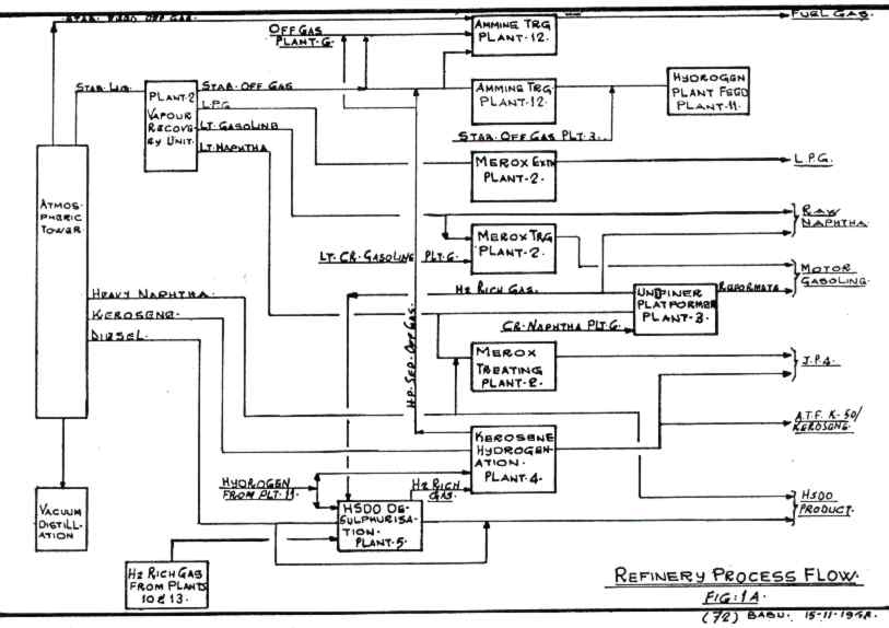
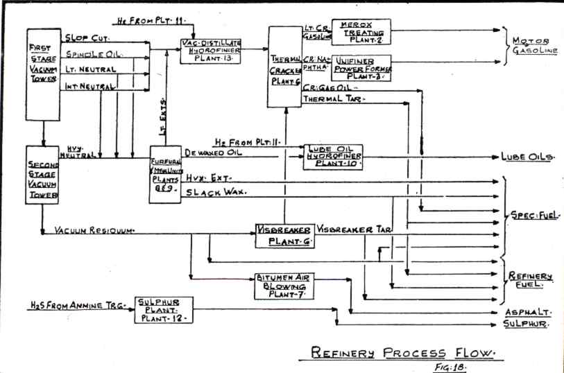
Refinery Process flow
A simplified sketch of the manner in which the crude oil is processed through various units is given in figures No. I A & B. The crude oil is separated into several fractions all of which require further processing or blending to meet the quality requirements. The separation is effected in atmospheric tower and two stage vacuum towers. The streams obtained are gas, overhead distillate naphtha, Heavy naphtha, kerosene, diesel from atmospheric tower and gas oil spindle oil, light neutral oil, intermediate neutral from first stage vacuum tower and heavy neutral and vacuum residuum from second stage vacuum tower.
The gas is used as refinery fuel gas along with the off gases from Unifiner (Pit. No. 3), kerosene hydrodesulphuriser (Plant No. 4) and thermal cracker and visbreaker (Plant No. 6) after recovering the Hz S by amine treating in plant 12.
The oveahead naphtha is sent to Vapour Recovery Unit (VRU) where it is split up into gas, LPG, Light straight run gasoline and light naphtha. The gas is used as feed to hydrogen plant after ammine treating. Light straight run gasoline (LSR) is partly blended to gasoline after merox sweetening and the balance is sent to naphtha pool. The light naphtha splits up into three steams. One of the steams is blended with kerosene to produce JP-4, the second is desulphurised in Unifiner and forms part of the feed stock for Platformer, and the balance is sent out to the naphtha pool untreated.
The light naphtha stream is reformed in Platformer to improve its octane number and blended to gasoline. Catalytic reforming of naphtha produces hydrogen as byeproduct which is used for desulphurising the naphtha feed to the Platformer in the Unifiner and the surplus is used in the otner desulphurisers.
The heavy naphtha 'stream from the atmospheric tower is the first side stream. Part of the heavy naphtha is sweetened along with light naphtha in plant 2 using merox catalyst to meet the blending requirements of JP-4. The balance will be blended with diesel oil draw off to produce high speed diesel oil.
The second side stream from atmospheric tower is kerosene. This draw off is adjusted to make Aviation Turbine fuel (ATF-K50) to meet the specifications whenever the plant is producing ATF-K50. The balance of the period the plant will be on Superior Kerosene
operation. The stream is desulphurised in the plant No. 4 with hydrogen and sent to product tankage. The third sidestream of the atmospheric tower is Diesel oil. Part of this is desulphurised in plant No. 5 using hydrogen. The raw diesel, desulphurised diesel and heavy naphtha form the components of high speed Diesel oil.
The bottoms product of atmospheric tower is the feed to the first stage vacuum distillation. Four streams are separated from the feed—gas oil, spindle oil, light neutral, intermediate neutral. These form the feed stock for the plants 8, 9 and thermal cracker. The spindle oil, light neutral and intermediate neutral streams required to meet the feed stock requirements of Furfural Extraction and dewaxing units are sent to intermediate tanks. The feed stock to the thermal cracker is desulphurised in plant 13. The cracked gas oil and thermal tar produced in plant 6 are used for blending fuel oil. The cracked naphtha product from plant 6 is used as part of the feed to the Unifiner and /Platformer. The light gasoline produced as a result of the cracking is used for gasoline blending.
The bottoms product of first stage vacuum tower is separated into vacuum residiuum and Heavy Neutral fractions in the second stage vacuum tower. Heavy neutral is drawn off as side stream and vacuum residuum is used partly as feed to the Visbreaker, partly to produce asphalts and the balance is blended directly as Refinery fuel or fuel oil. Asphalts are produced by air blowing of the vacuum bottoms. The heavy neutral is stored in an intermediate tank and is processed in Furfural Extraction and dewaxing units.
The Furfural unit processes the spindle oil, part of light neutral intermediate neutral and heavy neutral feed stocks on a blocked out operation to produce high and medium viscosity index lubrication oil components. Furfural extracts the aromatics which have low viscosity index from the feed stock, thereby improving the viscosity index of the lube component. The products from the Furfural unit are routed through the dewaxing unit through storage tanks. The extracted aromatics called lube extracts are sent to Vacuum Distillate Desulphuriser. The heavy neutral extract is sent to fuel oil blending directly.
Dewaxing unit processes all the finished Raffinate from Furfural extraction unit and also the low viscosity index streams of light neutral, intermediate neutral and heavy neutral. The unit removes the wax from the feed stock and improves the pour point of the product. The slack wax is blended directly to fuel oil and the finished products are sent to storage.
Lube oil hydrofinisher processes the finished lube oil components to improve colour stability, oxidation stability and remove part of the sulphur and nitrogen compounds. The dewaxed oil from unit is fed to the hydrofinisher (plant 10) on a blocked - out operation. The finished lube oil components are stored and blended to various grades of lube oil outside the refinery.
The HzS rich gases from plant Nos. 3, 4, 5, 10 and 13 are ammine treated to recover the H 2 S. The H 2 S thus recovered is converted into Sulphur in plant 12.