SPEEDTRONIC CONTROL SYSTEM OF GE
![]()
EXECUTIVE SUMMARY
The SPEEDTRONIC* Mark IV Control System is a derivative of the highly successful SPEED- TRONIC Mark I and Mark II gas turbine control systems. These predecessor systems were based on successfully automated turbine control, protection, and sequencing techniques that date back to the late 1940's, and have grown and developed with available technology. Electronic implementation of turbine control, protection, and sequencing originated with the introduction of the Mark I system in 1968. The Mark IV system is a digital implementation of the turbine automation techniques learned and refined over 40 years of successful experience, half of which has been through the use
of electronic control technology.
The SPEEDTRONIC Mark IV Control System employs current state-of-the-art technology, including triple redundant sixteen bit micro- processor controllers and two-out-of-three voting redundancy on critical control and protection parameters. Control and protection sensors are also triple redundant, and are distributed among the three control processors. System output signals are voted at logic relays for solenoids, and at three coil servo valves for analog control signals, thus maximizing both protective and running reliability.
The Mark IV Control System is designed to fulfill all gas turbine control requirements. These include control of either liquid, gas, or both fuels in accordance with the requirements of speed or load control und part-load conditions, temperature control under maximum-capability conditions, or open loop under start-up and shutdown conditions. In addition, inlet guide vanes and water or steam injection are controlled to meet operating requirements. Se-quencing of auxiliaries to allow fully automated startup, shutdown, and cool down are also handled by the Mark IV Control System. Turbine protection against adverse operating situations, and annunciation of undesirable operating conditions, are also incorporated into the basic control system. The local operator interface consists of a black and white, alphanumeric cathode ray tube (CRT)
to provide feedback to the operator regarding current operating conditions. Input commands from the operator are entered into the system from an industrial-grade membrane-switch panel, utilizing an arm/execute sequence to prevent inadvertent turbine operation. Communication between the operator interface and the turbine control is accomplished utilizing a fourth microprocessor, called the communicator, which also handles communication functions between control processors, thus reducing the potential for propagation of soft-ware and data errors. A backup LED display, directly connected to the control processors, is provided to allow continued gas turbine operation in the unlikely event of a failure of either the communicator microprocessor or the CRT.
The communicator also provides the interface for remote control and data logging using the GE DATATRONIC* Distributed Control and Information System. An optional arrangement, utilizing a redundant "hot backup" communicator, is available for those applications where integrity of the external data link is considered essential to continued plant operations.
Built-in diagnostics for troubleshooting purposes are extensive, and include "power-up", back* ground, and manually initiated diagnostic routines
capable of identifying both control panel and sensor or actuator faults. These faults are identified down to the board level for the panel, and to the sensor or actuator as appropriate. The ability of on-line replacement of boards is built into the panel
design, and is available for those sensors where physical access and system isolation are feasible. Set points, tuning parameters, and control constants are adjustable during operation, although a two-level security password system is utilized to prevent unauthorized access.
A printer is built into the control system, and is accessible through a drawer below the operator interface. The printer is capable of copying any display shown on the CRT. Since one of these displays is an operator-configurable demand display, this facility provides an easy means to obtain periodic and shift logs. The printer also automatically logs time-tagged alarms, as well as clearance of alarms. In addition, the printer has a
historical logging capability that prints critical parameters, historically backwards in time on a logarithmic time base, at the press of a membrane switch. Since the historical memory is frozen in the unlikely event of a turbine trip, this function is capable of capturing the cause of a trip for troubleshooting purposes.
CONTROL SYSTEM FUNCTIONS
The SPEEDTRONIC Control System performs many functions including fuel, air and emissions control, sequencing of turbine fuel, and auxiliaries for startup, shutdown and cool down, monitoring of all turbine control and auxiliary functions, and protection against unsafe and adverse operating conditions.
All of these functions are performed in an integrated manner which is tailored to achieve the previously described philosophy in the stated priority. The speed and load control function acts to con- trol the fuel flow under part-load conditions to satisfy the needs of the governor. The temperature control system limits fuel flow to a maximum consistent with achieving rated firing temperatures, and on heat recovery applications, controls air flow, via the inlet guide vanes, to maximize exhaust temperature. The operating limits of the fuel control are shown in Fig. 2. A block diagram of the speed, load, and temperature control systems is shown in Fig. 3. The input to the system is the operator command for speed, when separated from the grid, and load when connected to the grid. The output is the fuel command signal to the fuel control system. Provisions are shown for two types of variable droop or isochronous speed control, load control, speed matching for automatic synchronizing, temperature control, and minimum fuel control to prevent loss of flame on load rejection.
fig2.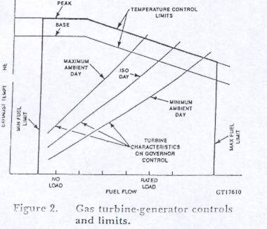
fig3.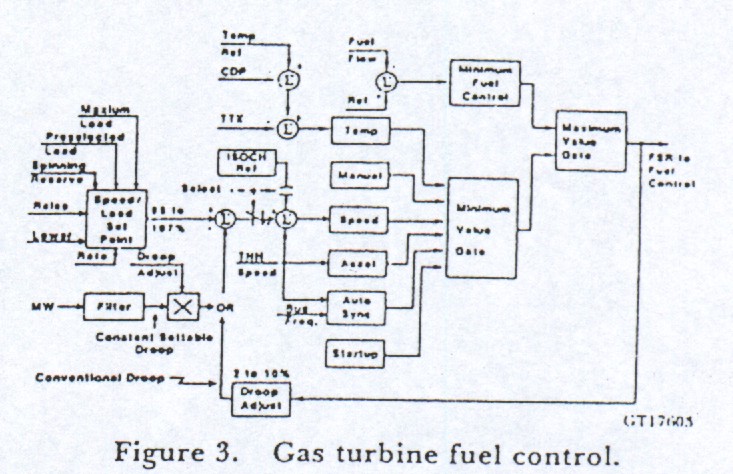
The fuel command signal is passed to the gas and liquid fuel systems in accordance with the seperator's fuel selection. Start-up can be on either fuel, and transfers under load arc accomplished by transitioning from one system to the other after an appropriate system fill time to minimize load excursions. Purging of the idle fuel system is automatic and continuously monitored to ensure proper operation. Transfer can be automatically initiated on loss of supply of the running fuel, which will be alarmed, and will proceed to completion without operator intervention. The gas fuel control system is shown schematically in Fig. 4. It is a two-stage system, incorporating a pressure control proportional to turbine speed, and flow control proportional to fuel command.
fig4.
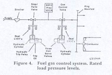
Two-stage control provides a stable turndown ratio of about one hundred to one, which is adequate for control under start-up and warmup conditions as well as maximum flow for peaking at minimum ambient temperature. The speed/ pressure ratio valve also acts as an independent stop valve, as it is equipped with an interposed hydraulically- actuated trip relay, which can trip the valve closed independently of control signals to the servo valve.
Both the stop/ratio and control valves are hydraulically-actuated, single-acting valves that will fail to the closed position on loss of signal or hydraulic pressure. Fuel distribution to the gas fuel nozzles in the multiple combustors is accomplished by careful control of fuel nozzle areas.
fig5.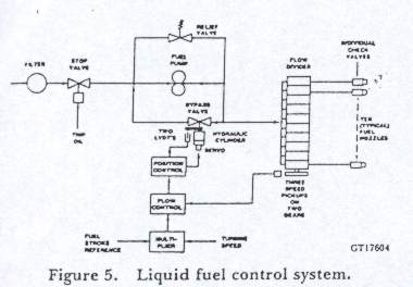
The liquid fuel control system is shown schematically in Fig. 5. Since the fuel pump is a positive displacement pump, the system achieves flow control by recirculating excess fuel from the discharge back to the pump suction. The required tundown ratio is achieved by multiplying the fuel command by a signal proportional to turbine speed. This signal positions the pump recirculation, or bypass valve, as appropriate to make the actual fuel flow, as measured by the speed of the liquid fuel flow divider, equal the product of turbine speed and fuel command. This results in a system in which both the liquid and gas fuel command signals are essentially equal. Fuel distribution to liquid fuel nozzles in the multiple combustors is achieved via the flow divider. This is a proven mechanical device,' which consists of carefully matched gear pumps for each combustor, all of which are mechanically connected to run at he same speed.
Control of nitrogen oxide emissions is accomplished primarily by the injection of water or steam into the combustors. The amount of water required is a function of the fuel flow, and is shown, for natural gas and distillate fuels in Fig.6. Accuracy of the flow control and system monitoring meets or exceeds F.PA requirements. An independent, fast-acting shutoff valve is provided to ensure against of loss of flame on sudden load rejection. The gas turbine, like any internal combustion engine, is not self starting and requires an external source of cranking power for start-up. This is usually a diesel engine or electric motor combined with a torque converter but could also be steam turbine or gas expander, if external steam or gas supplies are available. Start-up via the generator, using variable frequency power supplies, is also used on some of the larger gas turbines. Sufficient cranking power is provided to crank the unfired gas turbine at 25 to 30 percent speed, depending on the ambient, even though ignition speed is 10 to 15 percent. This extra cranking power is used for gas path purging prior to ignition, compressor water washing, and accelerated cool down.
fig6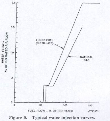
fig7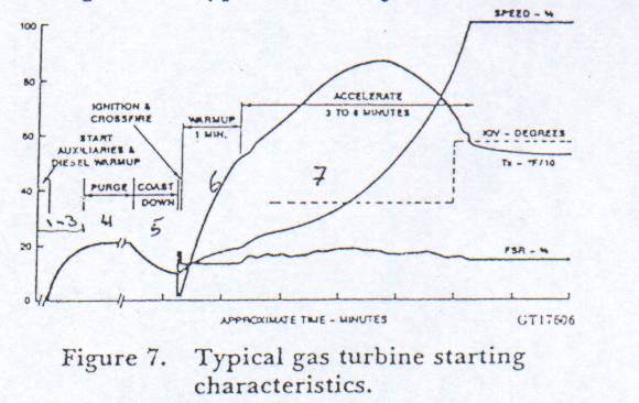
A typical automatic starting sequence is shown in Fig. 7. After automatic system checks have been successfully completed.-and lube-oil, pressure established, the cranking device is started, and for diesel engines allowed to warm up. When the turbine reaches purge speed, this speed is held for necessary purge period. Purge times will vary from one minute or less to as long as ten minutes in some heat recovery applications. When purging is completed, the turbine rotor is allowed to decelerate to ignition speed. This speed has been found to be optimum from the standpoint of both thermal fatigue damage to hot gas path components, as well as reliable ignition and cross firing of the combustors. The ignition sequence consists of turning on ignition power to the spark plugs and then firing fuel flow. When flame is detected by the flame detectors, which are on the opposite side of the turbine from the spark plugs, ignition and cross firing are complete, and fuel is reduced to the warm up value for one minute, while starting device power is brought to the maximum. In the unlikely event of incomplete cross firing, this situation will be detected by the combustion monitor as a high exhaust temperature spread, prior to loading the gas turbine.
After completion of the warm-up period, fuel flow is allowed to increase, and the gas turbine begins to accelerate faster. At a speed of about 30 to 50 percent, the gas turbine follows a predetermined program of acceleration rates, slower initially, and higher just. before reaching running speed. The purpose of this is to reduce the thermal fatigue duty associated with the start-up. At about 40 to 65 percent speed, turbine efficiency has increased sufficiently so that the gas turbine becomes self sustaining, and starting power
is no longer required. At about 80 to 90 percent, the compressor inlet guide vanes, which were closed during start-up to prevent compressor surge, are opened to the full-speed, no-load position.
As the turbine approaches running speed, the next step of the start-up, synchronizing to the running bus, is begun. This is a two step process that consists of matching turbine generator speed to the bus, and then closing the breaker at the point where the two are in phase within predetermined limits. Turbine speed is matched to the line frequency with a small positive differential to prevent the generator breaker from tripping on reverse power at breaker closure. Microprocessor- based synchronizing methods are used to predict zero phase angle difference and compensate for breaker closing to provide true zero angle closure. The final step in the starting sequence consists of automatic loading of the gas turbine-generator, at either a normal or fast rate, to either a preselected intermediate load or base or peak load.
Normal shutdown is initiated by the operator, and is reversible until the breaker opens. The shut- down sequence begins with automatic unloading of the unit. The main generator breaker is opened by the reverse power relay at about five percent negative power, which drives the gas turbine fuel flow to a minimum value sufficient to maintain flame but not unit speed. The gas turbine then decelerates to about 40 percent speed, where fuel is completely shut off. Again, the purpose of this fired shutdown sequence is to reduce the thermal fatigue duty imposed on hot gas path parts.
Subsequent to the shutoff of fuel, the gas turbine coasts down to a point where the cool down turning system can be effective. The rotor should be turned periodically to prevent bowing and resultant vibration on subsequent start-ups. Turning of the rotor for cool down or maintenance is accomplished by a ratcheting mechanism on the smaller gas turbines, or by operation of the torque converter output shaft from the auxiliary lube
oil pump on the larger gas turbines. Normal cool down periods vary from five hours on the smaller turbines to 24 hours on the larger units. Cool down sequences may be interrupted at any point for a restart if desired,
Gas turbines are capable of faster starting in the event of a system emergency. However, thermal fatigue duty for these faster starts is substantially higher. Therefore, selection of a fast start or emergency start is by operator action, with the normal start being the default case.
Gas Turbine-generators that are equipped with diesel engine starting devices are also optionally capable of starting in a blacked-out condition, without outside electrical power. Lube oil for starting is supplied by the DC emergency pump, powered from the unit battery, which also provides power to the DC fuel forwarding pump for black starts on distillate. The turbine and generator control panels are always powered from the battery on all units. Power for the cooling system fans is obtained from the main generator through the power potential transformer after the generator field is dashed from the battery at about 20 percent speed. The black-start option utilizes a DC battery operated turning device for rotor cool down to ensure the integrity of the black-start capability.
As mentioned previously, the protective function acts to trip the gas turbine independently, and the fuel control in the event of overspeed, high temperature, high rotor vibration, fire, loss of flame, or a loss of Lube oil pressure.
With the advent of microprocessors, additional protective features have been added, with minimum impact to the running reliability due to the redundancy the microprocessors, sensors, and signal processing. The added functions include combustion and exhaust thermocouple monitoring, axial flow compressor surge, high lube-oil header temperature, low hydraulic supply pressure, and more than one control computer fault.
Because of their nature or criticality, some protective functions trip the stop valve through the hard-wired master trip circuit as well as both through, and independently from, the three control processors. These functions include a hard-wired overspeed detection system, with independent sensors for systems that do not have a mechanical overspeed bolt chat directly trips hydraulic pressure. Still other functions, such as loss of lube oil, hydraulic supply, or trip oil, will also result in direct hydraulic actuation of the stop valves, which are spring loaded to close. A block diagram of the turbine protective system is shown in Fig. 8. Interfacing to other application specific trip functions are provided through the three redundant control processors, the master trip circuit or hydraulically. These will include turbine shutdown for generator protective purposes and combined- cycle coordination with heat recovery steam generators, and single shaft STAG* steam turbines, the latter being hydraulically integrated as shown in Fig. 8. Other protective coordination can be provided as required.
fig8.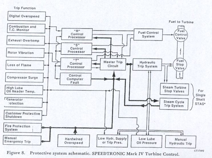
SPEEDTRONIC MARK IV SYSTEM CONFIGURATION
The fundamental concept underlying the SPEEDTRONIC Mark IV development is the utilization of microprocessor technology in a redundant configuration to optimize control flexibility and maximize running reliability, system availability and maintainability. The redundant design of the control system is complemented by redundant critical sensors and actuators to maximize system reliability, even in the event of component failures external to the panel. Extensive diagnostics ensures rapid identification of problems to minimize troubleshooting and repair time to improve availability. Information presented to the operator is expanded in both content and quality to allow the operator to make decisions more quickly and accurately.
The system architecture is illustrated in Fig. 9.There are three control processors, or sections, each with its own dedicated power supply and share of distributed sensors. Logic outputs from the three control processors are voted in a two-out-of-three format at output relays, which also provide isolation from outside electrical disturbances. Analog or continuously variable outputs signals are "voted" by an electromagnetic force balance process at the hydraulic actuator servo valves.
fig9.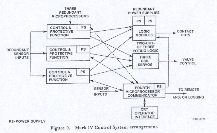
A fourth microprocessor, called the "communicator", handles all communication tasks between control processors to ensure against the propagation of software and data errors. The communicator also handles the operator interface, reading the operator input from the membrane control panel, and driving the CRT with operator feedback information. This processor also provides the interface for remote control and data logging functions. Finally, the communicator performs many of the non-critical control and monitoring functions-and diagnostics routines. A backup LED display, directly connected to the three control processors, provides operating information in the event that either the CRT or communicator are inoperative.
Critical sensors that are used for both control and protective functions arc redundant, or are connected in such a manner that equivalent redundancy is provided. The net result is chat no single sensor failure can cause a gas turbine forced outage. Furthermore, sufficient information is provided so that the diagnostic routines can detect
a failure and identify the failed sensor. A list of critical redundant sensors is shown in Table 3. Critical control sensors are dedicated to each of the three control processors and are voted at the processor outputs. Critical protective sensors are shared so that all processors read all sensors, effectively voting at the processor inputs.
One-third of the exhaust temperature thermocouple readings are sorted by each processor, highest to lowest, and a median, or average of the two median readings if the number is even, is used as a temperature feedback signal for each processor in performing the temperature control and protective functions. The advantage of utilizing the median rather than an average of all readings lies in the automatic rejection of high and low thermo- couple failures. The processors report all readings to the communicator for diagnostic and monitoring purposes. The communicator also develops a true exhaust temperature measurement, which is transmitted back to the controllers for long-term correction of individual controller medians.
Each control processor develops the required fuel command and actuator stroke signals on the basis of information available from its own dedicated sensors plus transmitted data from the communicator. These output commands, which are computed digitally, are converted to analog values prior to transmission to the appropriate servo-valve coil. The liquid fuel flow control loop, gas fuel pressure control loop, and all hydraulic position actuators are very fast response control loops, making it logical to use conventional analog control techniques. Analog feedback signals are also converted to digital information to allow comparison with the original command, thus preserving the
accuracy inherent in digital processing. This also provides the basis for output and actuator diagnostic5, as well as automation of actuator and fuel control system calibration procedures. Since the analog control loops are all designed as "proportional plus reset", or integrating controllers having zero error, the electromagnetic action of the three-coil servo valve is also median selection process. This is illustrated in the lower portion of Fig. 10, the upper half of which shows a typical actuator control. The diagram shows gas
control valve command and servo coil current response during a computer fault which drives one of the three commands to a high failure, causing coil current to saturate at the wide open value.
This is rapidly compensated for by the two remaining position controllers to maintain the same electromagnetic balance, and therefore valve position. The condition shown is at steady state, since all three coils act in unison during transients to maintain a high dynamic position loop gain. There are several options available for interfacing the system to the outside world for the purposes of remote control and equipment monitoring. The simplest involves hard wiring for remote control with limited monitoring as historically implemented for cable remote or telemetry control systems. An enhancement of this approach utilizes a one-way data flow of monitoring information over an industry standard RS-232C line, using the predefined SPEEDTRONIC protocol. These two versions are shown in Table 4. Other alternatives include a SPEEDTRONIC Mark IV CRT remote panel, which duplicates the Mark IV operator interface at a remote location, and the GE DATATRONIC plant control system. The four processors in combination with the equipment and human interfacing devices, form an integrated system that is specifically designed to perform the tasks of controlling, sequencing, monitoring, and protecting a gas turbine and its auxiliary and support systems in the most reliable fashion available today.
fig10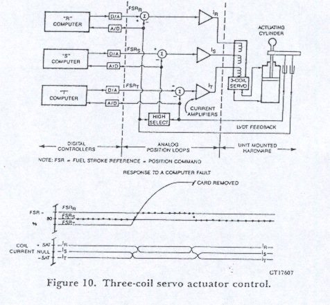
![]()
![]()