Overview of the 3500 Monitoring System of Bently Nevada
![]()
There are four main components to every 3500 Monitoring system.
1. Transducers
3. Software : Rack Configuration & Data Acquisition and Display
4. Computer with Windows compatible operating system
System Operation
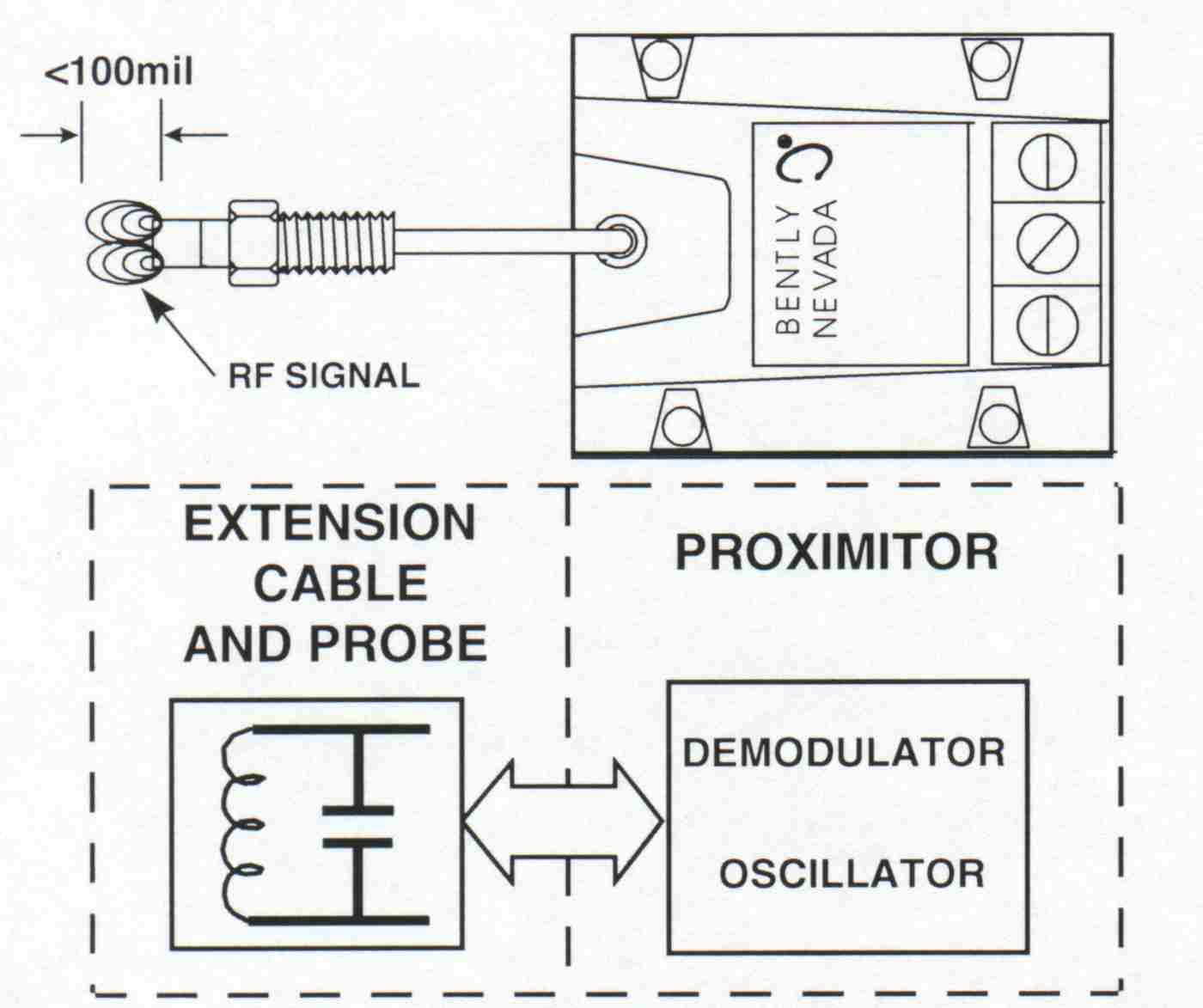
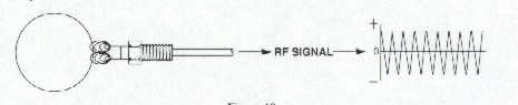
A. The Proximitor is an electronic device that has two basic functions:
1. Generates a radio frequency (RF) signal using an oscillator
circuit.
2. Conditions the RF signal to extract usable data using a demodulator circuit.
To do this it needs a -17.5 to -26 Vdc supply voltage connected between its VT and COM terminals.
B. Once the Proximitors oscillator has power it will generate an RF signal at a specific frequency. This frequency is dependent on the INDUCTANCE (L) value of the probes coil and the CAPACITANCE (C) value of the extension and probe cables.
The RF signal frequency will be within a range from 500 Kilohertz (KHz) to 2.0 Megahertz (MHz). Having a MISMATCHED transducer system (cable length too long or too short) will change the RF signal frequency and result in an incorrect Proximitor output.
The RF signal is transmitted from the probe coil which creates an RF field around the probe tip. The RF field extends to a distance greater than 0.1 inches (lOOmils), although only 0.08 inch (80mils) has to be linear.
C. When conductive material is present in the RF field, EDDY CURRENTS flow in the surface of that material. The penetration depth of the eddy currents depends on the materials conductivity and permeability. 4140 steel penetration is around 0.003 inches (3 mils).
If the material is to be plated, the plating must be done to a minimum of penetration depth.
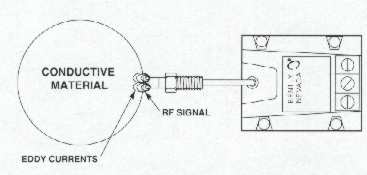
This ensures that the eddy currents are generated in the plating material which keeps the system output linear.
D. Once the probe is close enough to cause eddy currents to flow in a conductive material the RF signal is affected in tow ways :
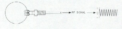
1. Amplitude is at a minimum when distance (GAP) between probe and material (TARGET) is at a minimum. Maximum eddy current flow occurs.
2. Amplitude is at a maximum when distance (GAP) between probe and material (TARGET) is at a Maximum. Minimum eddy current flow occurs.
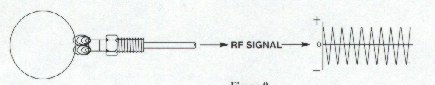
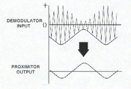
E. If the target is moving SLOWLY within the RF field, the signal amplitude INCREASES or DECREASES SLOWLY. If the target is moving RAPIDLY within the RE field, the signal amplitude INCREASES or DECREASES RAPIDLY. Oscillatory movement of the target causes the RE signal to modulate.
F. The demodulator circuit deals with a slow or fast changing signal amplitude in the same way. If the target is oscillating slowly (gap changing slowly) or NOT oscillating (gap not changing), the Proximitors output is a negative d.c. voltage, shown opposite by a dashed line. If the target is oscillating fast (gap changing fast) the Proximitors output is a varying d.c. voltage (a.c.) shown above by a sinewave. If the probe sees a vibration, the Proximitor will have a d.c. and a.c. component output. A typical system frequency response is from OHz (d.c.) to 10KHz.
APPLICATIONS
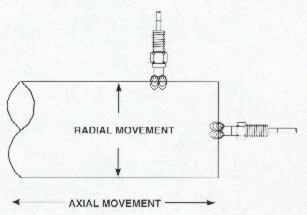
A. Proximity transducer systems have many uses in monitoring the behavior of a machine's shaft (target). The two most common being VIBRATION (radial movement) and THRUST (axial movement).
B. Another common use for the proximity transducer system is as a ONCE PER REVOLUTION marker or KEYPHASOR(Kf) on a machine shaft. This proximity transducer system is mounted so that it sees a "notch" or a "projection" on the shaft and produces a voltage pulse once each revolution.
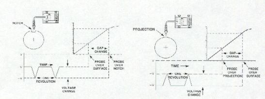
C. The Keyphasor is a very useful tool when diagnosing machinery problems. At a minimum, the generated pulse can be used to measure machine speed.
Performance Verification
A. The Proximitor is designed to give known output voltage changes equal to known gap changes. This is called a SCALE FACTOR. For the proximity transducer system the standard scale factor is set at 200 millivolts per mil (200mV/mil). Scale factor information can be found on the nameplate attached to the Proximitor. Scale factors are linear for a minimum of 80 mils within the systems linear range. Linear range can be shown graphically from which the scale factor can be calculated.
Average Scale Factor (ASF) =
change in gap voltage
change in gap = 18-2 = 200mV/mil
0.08in
A tolerance of ± 11 mV is allowed for Average SF (189mV/mil - 211mV/mil).
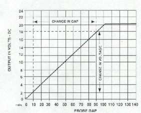
Note: Change in gap is within the 80mils LINEAR RANGE which is between lOmils and 90mils.
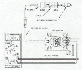
B. The graph above verifies the performance of a proximity transducer system. It is created by clamping the probe and a spindle micrometer, with a target attached, in a bracket. With the spindle micrometer set at ZERO the probe is clamped so that it reads electrical zero. Gap is increased by rotating the spindle micrometer away from the probe in 5 mil increments and noting the Proximitor output D.C. voltage at each step.
C. If the performance graph does not fall within specified limits, i.e., LINEAR RANGE less than 80mils, ASF outside ±1 ImV, the reason may be one of the following problems.
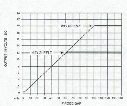
1. The -17.5 to -26Vdc supply to the Proximitor is out of tolerance.
The top graph shows effects of supplying the Proximitor with a lower voltage of -16Vdc. Although the SF is within limits the LINEAR RANGE has been severely reduced.
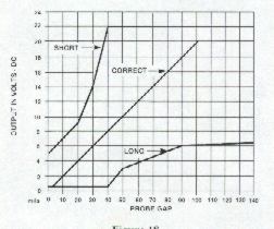
2. One of the system components is mismatched. PROBE, EXTENSION CABLE or PROXIMITOR is mismatched in electrical length making overall length too long or too short. The bottom graph shows effects of having a mismatched system. Where the graph shows a curve that is too LONG a 5 meter (50) Proximitor is used with a 9 meter cable (extension plus probe). Where the graph shows a curve that is too SHORT a 9 meter (90) Proximitor is used with a 5 meter cable (extension plus probe).
3. The Proximitor is calibrated to a different target material than the one used. If the Proximitor nameplate does not give target material information, the target material must be E4140 Steel. The following graph gives examples of the effect of different materials when observed by a Proximitor calibrated to a E4140 Steel target.
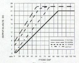
The Proximitor can be re-calibrated for some different target materials. This is done by changing the value of the calibration resistor located under the nameplate.
![]()
![]()
![]()
![]()
![]()
![]()