FUNCTIONAL DESCRIPTION OF ABB GAS TURBINE / GENERATOR
The gas turbine is composed of 3 processing elements, a compressor, a combustion chamber and the turbine itself.
The turbine converts the chemical energy contained in the fuel into mechanical energy at the coupling and is the prime mover that drives the generator.
The turbine is driven by hot, compressed combustion gas that strikes blading mounted on the rotor, and causes it to turn. After the combustion gas passes through the turbine it is discharged to atmosphere and is called exhaust gas.
The combustion gas that drives the turbine is supplied by the combustion chamber which is an enclosed, pressurized firing place where air and liquid and/or gaseous fuel are continuously burned.
The pressurized air required for combustion is delivered by the compressor, which is driven by the turbine through a common shaft. The air within the compressor is pressurized with the help of rotating and stationary blading.
The fuel throughput to the combustion chamber is controlled by the appropriate setting of control valves, which can assume, hold and change to any position between fully closed and fully open.
GENERATOR
The generator is the driven machine that converts the mechanical energy of the turbine into electrical energy. It is composed of a non-movable part called the stator and a movable part called the rotor. The latter is coupled to the turbine rotor, either directly or through a rotational speed reduction gear.
The rotor is basically a magnet that creates a rotating magnetic field inside the machine by means of the excitation or field winding, often referred to simply as the rotor winding.
To keep the generator in synchronism with the grid and maintain both generator voltage and the reactive power supplied to the grid within specified limits, the strength of the magnetic field must be adjusted to correspond to the electrical load on the generator This is accomplished by means of a direct current (referred to as an excitation current) passed through the rotor field winding. The excitation current in turn is controlled by the automatic voltage regulator (AVR) equipment which controls both the terminal voltage of the generator and the reactive power flow to the grid.
The stator contains fixed windings inside which an alternating voltage is induced by the rotating magnetic field.
Gas Turbine Basic Process
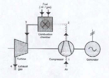
The process which takes place within a gas turboset is represented with symbols in the upper part.
Here we see illustrated the functional principle of the gas turboset.
Air is drawn in from the atmosphere, is pressurized in the compressor and is delivered to the combustion chamber.
Fuel and air are continuously burned in the combustion chamber and hot, pressurized combustion gas is delivered to the turbine.
The combustion gas is expanded through the turbine where it drives the complete shaft line composed of the turbine-compressor rotor and the generator rotor. The gas is then exhausted to atmosphere.
Electrical energy is continuously supplied by the generator.
System Overview
Egatrol is the ABB GT’s control and monitoring system using Advant Power.
The main Egatrol system features are :
INTEGRATED SYSTEM PERFORMING
Process control
Operation, monitoring and supervision
Information management applications
Integration of the GT power plant by serial link into the DCS
Engineering Documentation & service
SYSTEM STRUCTURE
The overall control system structure consists of
1. Process Interface
Open Loop control for drives and sequencers
Closed Loop control for process functions & control
Protection control in a 3 channel system with 2oo3 voting
2. Process stations,
The process stations performs the process I/O, control functions and data communication.
3. User Interface Stations
The user interface stations are :
Operator Station OS performing plant operation, monitoring & supervision
Information Management Station performing the plant management and information
ES Engineering station performing the engineering, documentation and service.
4. Communication networks
The redundant control netwrrk MB300 provides the communication of the time process data between the Egatrol stations and the operator interface stations.
The plant network TCP/IP provides communication between computers and peripheral units
5. The peripherals
Serial link to DCS
Interface to MCM system
ENGINEERING FUNCTIONS
Database dimensions, parametering, function selection & management
Process control dimensioning, programming, editing and on line modification
Source code loading and download of application program and database to CPU
Testing and fault tracing
Graphical displays creation for operation
History and Reports creation for information management
Back up and restore of application programs
Forcing of inputs and outputs
Reading and setting of data and time
Display transfer in OS
OS station updates
IMS station updates
![]()
![]()