|
|
|
Republic of the Philippines |
|
Department of Education |
|
Region I |
|
SCHOOLS DIVISION OFFICE I PANGASINAN |
|
AGUILAR INTEGRATED SCHOOL |
|
Aguilar, pangasinan |

Information
and Communications Technology
Computer
System Servicing
Module
1: Install Computer System and Networks Code: TLE_IACSS9-
12ICCS-Ia-e-28 20
Weeks
Quarter
1
PREPARED BY:
CARIDAD
V. OROGO
TEACHER
II
Lesson Information 1.5 Week 7
Applying 5’s on your
computer
The 5s comes from the Japanese word and translated
into English this is the standard process in working productivity process. It’s purpose is to help you make a
decision making process in standardization of work.
1. Seiri Sorting/Putting things in
order (Remove/discard what is not needed so that there are fewer hazards and
less clutter to interfere with work. Only keep what is needed.)
Example: Sorting of Lastnames alphabetically from A to Z.
2. Seiton Orderliness/Proper
Arrangement (Place things in such a way that they can be easily reached
whenever they are needed. "There must be a place for everything, and
everything must be in its place.")
Example: In your bag
it can easily find your ballpen if you place in the
pocket of your bag or pencil case.
3. Seiso Clean/cleanliness. (Keep
workplace and things clean and polished; no trash or dirt in the workplace)
Example:
cleaning your bedroom is comfortable to use.
4. Seiketsu Standardize/Purity
(Maintain cleanliness after cleaning, consistentlyperpetual
cleaning. Such cleaning is part of every one's work.)
Example:
cleaning of your bedroom nicely it means that if you cleaned your bedroom make
sure it is properly clean the quality of your work to clean.
5. Shitsuke Sustaining/discipline/commitment
(Maintain standards and keep the facility in safe and efficient order day after
day, year after year.)
Example: cleaning your
bedroom as your daily routine is the self-discipline.
This
Story Telling will show you the example of 5s: Watch my video lessons sent to
your group chat.
Lesson Information 1.4 Week 7
Data
Definition
Chemical hazard any hazard that results
from the accidental caused by toxic chemical.
Desktop computer is a personal computer
(PC) in a form intended for stationary use.
Electric shock Characterized by pain and
muscular spasm cause by an electric current.
Elimination The process of removing the hazard from the
workplace.
Ergonomics The science of designing the workplace environment
to fit the user.
Hazard A situation that has the potential to harm the
health and safety of people.
Hazard control the development of
systems to prevent accidents or injuries.
Health The general condition of a person in all aspects.
Housekeeping Is the systematic process of making a home neat and
clean and in order.
Risk A potential condition that a chosen action or
activity causes.
Risk management the process of analyzing
exposure to risk and managing it.
Safety The state of being "safe".
Standards Something accepted as a basis for comparison.
Tree structure an algorithm for placing
and locating files in an organized database.
OSH Occupational safety and health
PPE Personal protective equipment
Hazard Identification, Risk Assessment, and Risk Control
Occupational safety and health (OSH) is a
planned system of working to prevent illness and injury where you work by
recognizing and identifying hazards and risks. Health and safety procedure is
the responsibility of all persons in the computer and technology industries.
You must identify the hazards where you are working and decide how
dangerous they are. Eliminate the hazard or modify the risk that it presents.
There are three steps used to manage health and safety at work:
1. Identify the Hazard. A hazard is anything that could hurt you or
someone else.
The common hazard are the
following:
Physical Hazards is a circumstances that can hurt you
physically.
Example:
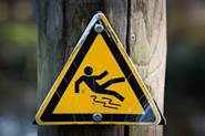
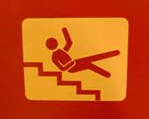
Falling from ladder slippery
Mechanical Hazards is a powered by manual or automatic machine that
can be resulted to injury.
Example:
Holding cpu fan can hurt you a mechanic may stuck his
hand into the machine
Chemical Hazards is a toxic chemical or exposure to chemicals in the workplace
can cause acute or long-term detrimental health effects.
 Example:

Printer Ink results to poison muriatic acid results to poison
Electric Shock Hazard can be defined as a dangerous condition where a worker could
make electrical contact with energized equipment or a
conductor, and from which the person may sustain an injury from shock; and/or,
there is potential for the worker to receive an arc flash burn, thermal burn,
or blast injury.
Example:

Electric wire
line man
Lesson Information 1.6-1
Week 8-10
ASSEMBLE
COMPUTER HARDWARE IN ACCORDANCE WITH ESTABLISHED PROCEDURES AND SYSTEM
REQUIREMENTS
SAFETY
PRECAUTIONS
Personal
Protective Equipment (PPE)- It
refers to protective clothing, helmets, goggles, or other gear designed to
protect the wearer's body or clothing from injury by electrical hazards, heat,
chemicals, and infection, for job-related occupational safety and health
purposes.
PPE
can also be used to protect the working environment from pesticide application,
pollution or infection from the worker (for example in a microchipfactory).
It is important that students and teachers during their laboratory period
should be required to use personal protective equipment. Some of these are:
|
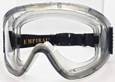
Goggles A
large spectacles, with shields around the rims, for protecting the eyes from
dust, excessive light, wind, etc. |
|
|
Rubber Sole A
special type of shoes used to prevent electrical shock and for waterproofing
and insulating purposes or any rubber shoes. |
|
|
Apron A
garment worn over the front of the body as a protection for one’s cloth. |
|
|
Face Mask A
covering for the face to prevent the inhaling or absorbing dust and other
chemicals |
|
|
|
|


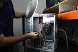
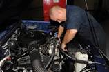
Personal Computer Disassembly
Before starting computer disassembly,
make sure you have the tools you need in disassembly and apply OHS with PPE.
Tools:
Screw driver
Clean cloth cotton
Paint or make up brush (dry and clean)
Part retriever
ESD Wrist wrap
PPE Tools
Before doing disassembly make sure you ground yourself. To ground
yourself you have to discharge your static energy from your body by holding
thru your hands in concrete walls or metal object make sure your hands are not
wet.
Step1. Wear PPE or Personal Protective Equipment
Step1. Unplugging - The first thing you do is to unplug
every cable that is plugged in to your computer. That includes the cables such
as Power, USB, Mouse, Keyboard, Internet, Ethernet, Modem, AM\FM Antenna, Cable
TV, etc. Just unplug all the cables for safety purposes.
Now that your computer is fully
unplugged, move your PC to a clean work space.
Step2.Opening the Outer Shell/Case- First, unscrew the four screws at the
back of the computer. On most computer cases, there will be large knobs that you
can unscrew by hand or by screw driver on the back-right side of the computer.
The left side has small screws because on that side you can't access much on
the inside.
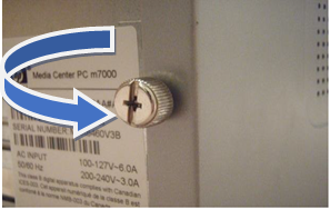
Figure 1. Screw at the back of computer chassis
Once the screws are removed, you can remove the side panels. On
most computers, they just slide off. Start with the left side panel (the side
that once had the knobs), slide it towards the back of the computer. Now you
can remove the left panel. Just like the other side, slide it towards the back
of the computer.
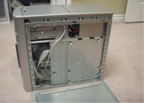


Figure 2. Removing the side panel
NOTICE: If you are working on a carpet, about every five minutes touch
something that is grounded (Sink faucet / pipe, wire coming from the ground part
of a wall outlet). This is done so you do not shock your motherboard or other
parts.
Step2. Remove CMOS Battery- Removing CMOS Battery first is essential because it supply
power source to mainboard to avoid damage to its parts of main board. To remove
CMOS Battery slide it out from the its outer part.
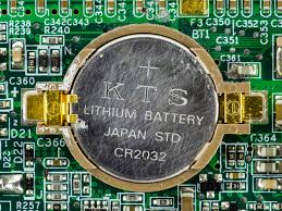
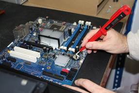
Figure 3. Removing the CMOS Battery
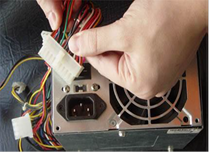
Step3. Power Supply Unit - The first thing to do is unplug every
wire coming from the power supply. You must disconnect the motherboard (very
large connector/plug), CD/DVD drive(s) power, internal hard drive power and
portable hard drive slot power.
power supply in place, on the back of the computer. Next, push the
power supply from the outside, and then lift it out.
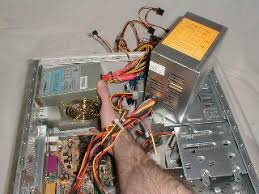
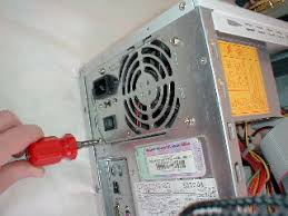
Figure 4. Removing the Power Supply Unit
Step4. CD/ DVD Drive(s)-First,
unplug the ribbon from the back of the drive. Once that is completed, pull on
the tab securing the drive in place, then push it out from the inside.
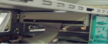
Figure 5. Removing the DVD Drive
 Step5.
Hard Drive - First, unplug the connector at the back
of the slot, and unplug the other end from the motherboard. Also unplug the
SATA cable from the motherboard and the hard drive. The portable hard drive
slot is secured the same way the CD/DVD drive is, with a tab. Pull on the tab,
then slide the slot out.
Step5.
Hard Drive - First, unplug the connector at the back
of the slot, and unplug the other end from the motherboard. Also unplug the
SATA cable from the motherboard and the hard drive. The portable hard drive
slot is secured the same way the CD/DVD drive is, with a tab. Pull on the tab,
then slide the slot out.
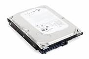
Figure
6. Removing the Hardisk
Drive
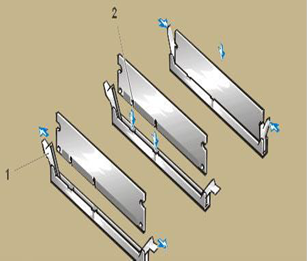
Step6. Memory (RAM) - To
remove the RAM, push down on both tabs holding the RAM in place, which are
located at both ends of the RAM.
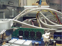
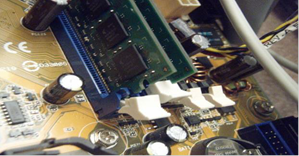
Figure 6. Removing the RAM Memory
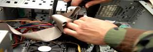
Step8.
Removing the CPU- Separate the CPU cooler or heatsink with fan from
the motherboard, Be gentle when
lifting the CPU cooler from the motherboard. Depending on the cooler, you can
also try to slide it back and forth to dislodge it. Be sure to this maneuver
gently though to prevent damaging it. Sometimes, thermal compound between the
CPU cooler and processor can settle in like glue so be sure not to yank the
cooler. Pulling the cooler too hard can yank the CPU out of its socket,
damaging itself and the socket. If a pin remains inside a socket, your
motherboard becomes permanently damaged as you won’t be able to replace the
socket itself.
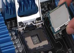
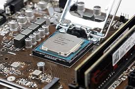
Figure 6. Removing the CPU
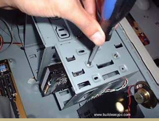
Step9. Motherboard - The
motherboard has seven screws holding it to the frame, which are indicated by
large white circles around them. Remove them and then lift the motherboard out
of the frame.
Figure 6. Removing
the Motherboard
Personal Computer Assembly
Now that you have the skills in disassembling a personal computer,
Ibelieve that you are ready to take another step of
this module which is assembling a personal computer. All you need to do is to
follow the step by step procedures provided in this module.
Step 1. Prepare your workplace
1. Take Inventory:
Before you start, take an inventory of
your parts. Do not begin assembling your computer if you don't have everything
you need. Begin the step-by-step process once you are ready with everything you
need.
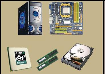
Figure 7. Take inventory of the Different Computer
Parts
2. Make Space, Make Time:
Building a PC takes up space - about a dining room table worth. So make sure
you have plenty of working room and a few hours to proceed with minimal
interruption. Work on a flat, stable table top surface, or bare floor, where
you have room to layout all of the items.
3. Prepare
Grounding Protection:
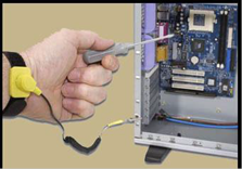 Use an inexpensive antistatic wrist strap. Make sure you are
wearing your antistatic wrist strap correctly (it does you no good at all if
you do not wear it!), and you are ready to proceed. Look at Figure 8 for
details.
Use an inexpensive antistatic wrist strap. Make sure you are
wearing your antistatic wrist strap correctly (it does you no good at all if
you do not wear it!), and you are ready to proceed. Look at Figure 8 for
details.
Figure
8 Wearing the Anti- static Wrist
Strap Correctly
4. Have the Drivers Ready:
Assuming you have another internet
connected PC, download the latest drivers from the vendors' websites for each
component you will be installing. Sometimes drivers are updated between the
time the component was manufactured and the time you are installing it. It is
always best to have the latest. Copy them to a CD for easy access.
 Step 2. Prepare the Motherboard
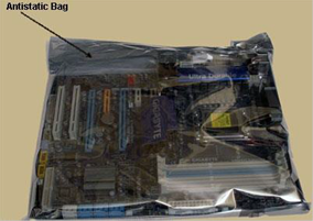
1. Great care should be taken when
installing the motherboard. First, take the
board out of its packaging and put it on
top of the antistatic bag it came in (see
Figure 45). Remember, you always want
to safeguard your components from
potentially hazardous static electricity
(wear your
strap).
Figure 9 Motherboard
in anti-static bag
2. Before you secure the motherboard
onto the PC case/chassis, inspect it carefully for any visible defects.
3. Next, review the motherboard manual,
to make sure you are familiar with the motherboard layout and understand which
socket is which. Manuals are extremely helpful, usually easy to read, and
include illustrations. Below you can find instructions on how to install the
processor, the heat sink and the memory modules on the motherboard. You should
not place the motherboard in the computer case until you are told to do so.
Step 3. Install the CPU
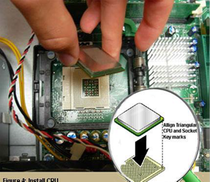 1. Use the unlocking mechanism to
open the CPU socket which is
usually a lever.
2. Carefully line up the pins and
place the chip in its socket; it will
fit only when oriented the proper
way. An arrow or a missing pin on
one corner of the chip will show
you how to line things up.
3. Align Triangular CPU and socket
key marks as shown in Figure 46.
4. Lower the lever to lock the CPU
into place. Figure 10 Install CPU
Step 4. Install the CPU Heat Sink
1. Follow the manufacturer's directions
to install the heat sink and the fan that will cool the processor. If you
bought an OEM CPU and a separate heat sink, you may need to spread a thin layer
of the thermal grease that came with the heat sink over the chip to ensure
proper transfer of heat (some heat sinks come with this grease already
applied).
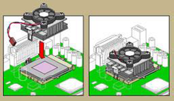
Figure 11 Install CPU Heat Sink
3. Attach the clip that holds the heat sink in place keeping in
mind that it may require a fair amount of force. Again, follow the instructions
that came with the heat sink. They will show you how to fit it correctly. If
you are in doubt, you can visit the manufacturer's website for more
information.
4. Plug the CPU fan's power connector
into the proper connector on the motherboard.
Step 5. Install Memory (RAM Modules)
 In order to install the memory modules,
insert them into the proper sockets (Figure 48) and push down firmly but evenly
until the clips on both sides of the socket pop into place. If your motherboard
supports dual-channel memory, consult the user manual to determine which pairs
of RAM sockets you should use. The motherboard and the CPU are the brain and
nerve center of your PC, so selecting these components is the most important
decision you'll make. Figure 12 Install
RAM Module
In order to install the memory modules,
insert them into the proper sockets (Figure 48) and push down firmly but evenly
until the clips on both sides of the socket pop into place. If your motherboard
supports dual-channel memory, consult the user manual to determine which pairs
of RAM sockets you should use. The motherboard and the CPU are the brain and
nerve center of your PC, so selecting these components is the most important
decision you'll make. Figure 12 Install
RAM Module
Step 6. Place the motherboard into the
case
1. Some PC
cases have a removable motherboard tray. If yours does, remove the screws
holding it in place and pull it out of the case (Figure 13).
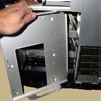
Figure 13. Remove Motherboard Tray
2. Note the pattern of the holes in your motherboard
(Figure 14), and screw brass standoffs into the motherboard tray or into the PC
case in the correct locations (ALWAYS check the manual and follow their
instructions to the letter).
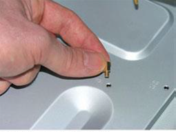
Figure 14.
Screw Brass Standoffs Into the Motherboard
3. Check the layout of the sockets on
the motherboard, and confirm that the ports on your motherboard's back panel
match the holes on the case's Input/Output (I/O)
shield that is installed in your case. If necessary, remove the old I/O shield
by tapping it firmly a few times with the butt-end of a screwdriver, and then
replace it with the shield that came with the new motherboard.
4. Carefully
position the motherboard on top of the brass standoffs (Figure 15), line up all
the holes, and use the screws that accompanied the case to fasten down the
motherboard. If you are using a removable tray in your system, slide the tray
and motherboard back into the case and then secure the tray.
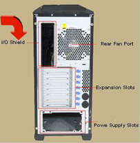
Figure
15. Case’s I /O Shield
Figure
16. Mount the Motherboard
Step 7.
Install Graphics / Video Cards
1. Begin by removing the
backplane cover from the AGP or PCI Express X16 slot (the metal piece where the
monitor connector will emerge) (Figure 17).
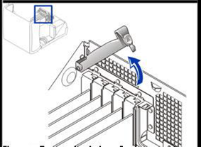
Figure
17. Remove the backplane cover
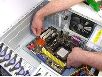
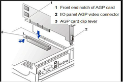 2. Install the graphics board in
that slot, and then secure the card with a screw (Figure 18).
2. Install the graphics board in
that slot, and then secure the card with a screw (Figure 18).
Figure
18. Install the Graphics Board
Step 8. Install Internal Drives
Now it is time to install your drives.
This is an easy process, but it requires attention to detail.
1. Make any necessary changes to jumpers on the drives before
mounting them in the case. A two-drive system (one or two SATA (Serial ATA-
is a standard hardware interface for connecting hard drives and CD/DVD
drives to a computer) hard drives, plus one parallel ATA (Advanced Technology
Attachment) optical drive, for example) is easy to set up; the SATA drives are
jumper less, and the optical drive can be set as master on its own parallel ATA
channel. Many cases have removable drive rails or cages to house drives.
 2. Use the included screws to attach your drives to the
rails or cage, and slide them into the case. For externally accessible drives
such as a DVD recorder, you can save time by installing one drive rail and
sliding the drive in for a test fitting to make sure that its front is flush with
the case (Figure 19).
2. Use the included screws to attach your drives to the
rails or cage, and slide them into the case. For externally accessible drives
such as a DVD recorder, you can save time by installing one drive rail and
sliding the drive in for a test fitting to make sure that its front is flush with
the case (Figure 19).
Figure 19.
Attach your devices
Step 9. Install the Add- in Cards
1. For each add-in card, you must choose a free PCI slot.
1. Remove its backplane cover to allow access from the rear of the
case.
3. Carefully position the card above the slot, and press down
firmly to seat the card (Figure 20).
4. Secure the card with a screw.
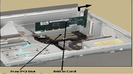
Figure
20. Add- in Cards
Step 10. Connect the Power Supply
Making the proper connections is
crucial to successfully assembling your PC system. Fortunately, manufacturers
provide color-coded power cables and unique connector shapes to make the job
easy.
1. First, plug the large ATX power
connector (Figure 21) from your power supply into the matching port on your
motherboard. Look Figure X for details.
2. Locate the smaller, square processor
power connector (Figure 54) (you cannot miss it - it is the one sprouting the
yellow and black wires) and attach it to the motherboard. Note: your
connector is usually located near the processor. As always, refer to your
motherboard's manual for the exact locations.
3. Use your motherboard user manual and
find the description about front-panel connectors.
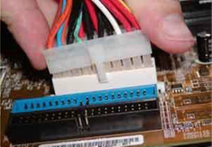
Figure
21. Connect the ATX Power in the
Motherboard
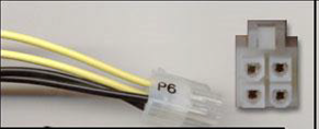
Figure
22. Square Processor Power
Connector
NOTE:
You are going to be doing work that
requires attention to detail and can be quite frustrating if you do not go into
it with the right attitude.
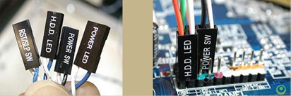 4. Attach each of the tiny leads from the power and reset
switches (Figure 18), the hard-disk activity lights, the PC speaker, and any
front-panel USB and FireWire ports to the corresponding pin on your
motherboard. The needle-nose pliers are useful for manipulating small pieces.
4. Attach each of the tiny leads from the power and reset
switches (Figure 18), the hard-disk activity lights, the PC speaker, and any
front-panel USB and FireWire ports to the corresponding pin on your
motherboard. The needle-nose pliers are useful for manipulating small pieces.
Figure
23. Connect the different Leads
When the drives are installed, connect
power and data cables to each one. Parallel ATA drives use wide, flat data
cables that can be installed only in the correct way. Floppy drives use a
similar but smaller cable; SATA drives use a thin, 1cm-wide data cable. SATA
drives use a new type of power connector that many power supplies don't come
with. Fortunately, many motherboards ship with adapters for converting a
standard four-pin power connector to a SATA power connector (Figure 23).
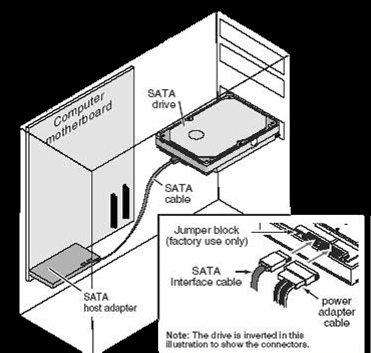
Figure
23. Connect Power Connector
Step 10. Install CMOS Battery
To install
CMOS Battery locate the battery slot and insert it to the slot as shown in
figure 24.
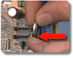
Figure 24.
Insert CMOS Battery
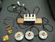
Many motherboards have additional sound
connectors or ports housed on small add-in boards. Some of these plug into
slots on the motherboard; others screw into the back of the case in place of
slot covers. Usually the additional ports are not essential to your PC's
operation. For example, if you install a sound card, you do not need connectors
to the motherboard's built-in sound chip. Check your motherboard manual to
determine what each of these boards does.
Connecting Peripherals of a Personal
Computer
When attaching hardware and peripherals
of the computer, ensure that they are connected to the correct locations or
ports. For example, some mouse and keyboard cables use the same type of PS/2
connector. So, you must know first the different ports that can be found in the
back panel of the computer.
Steps in Connecting Peripherals of a PC
Step 1.Attach the monitor cable to the video
port.
Step 2.Secure the cable by tightening the
screws on the connector.
Step 3.Plug the keyboard cable into the PS/2
keyboard port.
Step 4.Plug the mouse cable into the PS/2
mouse port.
Step 5.Plug the USB cable into a USB port.
Step 6.Plug the network cable into the network
port.
Step 7.Plug the power cable into the power supply.
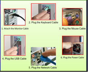
Figure
25. Steps in Connecting Peripherals
of a PC
After
connecting all the cables into their proper places, the picture in the next
page should be the appearance of the back panel of your PC.
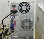
Figure 26. Appearance of the PC’s Back Panel