This page is about radio controlled model servos (RC servos for short). These things have the servo amplifier, servo motor, gear reduction, and the feedback pot in the same small case. It is a position servo(which means that you tell it what position to go to), with a range of about 180 degrees. They have three electrical connections; Vcc, GND, and control input.
Also, see a simple explanation of FM RC baseband signals, TX, RX, etc to see how they are used in their intended application.
To control the servo, you command it to a certain angle, measured from 0 degrees. You send it a series of pulses. The ON time of the pulse indicates the angle to turn to; 1ms = 0 degrees, 2ms=max degrees(about 120) and anything in between gives a proportional output angle. 1.5ms is generally considered to be the "center". The 1~2ms limit is manufacturers' recommendations; you can usually use a wider range around 1.5ms for grater throw. I did not do this, but you can use pulses of less than 1ms, and more than 2ms for an output angle of 180degrees or more. The limiting factor is the feedback pot and the mechanical limits built in the servo. A buzzing sound usually indicates that you are trying to over drive the servo, and should back off a little.
The OFF time of the pulse train fed into the servo is not critical; it can be anything around 20ms. I have used 10ms to 30 ms. It does not have to be fixed either, it can vary from one pulse to another, and it actually does so in real RC equipment. Pulses occurring more frequently than the minimum OFF time spacing are likely to interfere with the internal servo timing, and you might get a buzzing sound with vibration of the output arm. If the pulse spacing is greater than about 50ms (manufacturer dependent), then the servo will go to sleep mode in between pulses. It will move in small steps and the output will be jerky.
This is an example of what the signal to the servo should look like:
     ____                  ____             _____            _____
  __|    |________________|    |___________|     |__________|     |__
The OFF time is varying, as you can see. This has no adverse effects as long as it is between about 10~30ms. The ON time determines the position of the output arm.
Beware that there are old servos which used inverted pulse polarity (i.e. where OFF time is important). They are quite hard to come-by these days. Also, I have read in the newsgroups that some RC car servos have a different "center" pulse timing and different pulse ranges. Not common either. But if you happen to have one of these servos, all you have to do is to change your pulse timing or polarity! The rest is the same.
To command it to 30 degrees; you calculate the pulse length: 0 degree=1ms, 120 degree=2ms => 30 degree=1.16ms. Linear relationship. So if you keep sending it 1.16ms pulses, it will go and hold its position at 30 degrees. If there is an external force that tries to move it away, the servo will actively try to resist it (that is, if the arm is moved externally, the servo will give motor inputs to correct the error).
It is also possible to stop sending the pulses after the servo has moved to its position. If you stop sending pulses for more than about 50ms (depends on the servo), it will power down. That means, it will not be applying any motor inputs, or actively resisting external forces; only friction will hold the output arm in place.
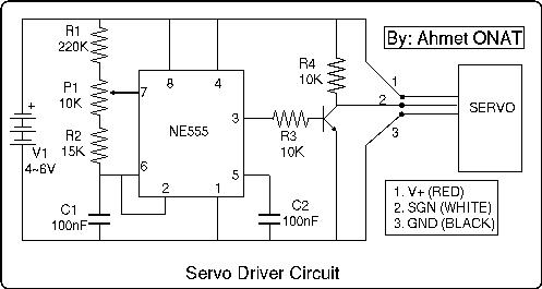
Here is my version. I have built it, and have been using it for more than a year now. You can use it just to play with servos, to check that they work, or you can plug the servos in your robot, first to this driver, and find the required pulse times with an oscilloscope to program into your microcontroller. I hope you will benefit from it. As usual, this circuit is "as is", not guaranteed to do anything useful, and I disclaim any responsibility from any damage that can be caused while building or using it.(that should keep the lawyers happy!-see the disclaimers)
If you cannot see this clearly, here is a larger version (45K)
It uses the popular 555 timer IC. Usual name is NE555, but almost all IC manufacturers have done it. Sometimes also listed as 7555. If you can't find it, go throw yourself off a cliff (^_^)! The schematic is straight off the data sheets, with the resistor/capacitor values calculated from the formulas there. The only difference is the presence of P1, which changes the time constant as you move/turn its spindle.
The signal at the output of the IC (pin3) has the wrong polarity. To invert it to norma, the transistor is necessary. The transistor is connected in "common collector" configuration and is used in saturated mode (that means it is either full on or full off), so any npn transistor you might care to connect should work without any problems (mine is a C1959Y; straight from the jun... -err, recyclable items box).
In case you cannot read the values, here is a parts list:
R1: 220K
R2: 15K
R3: 10K
R4: 10K
P1: 10K
C1: 100nF
C2: 100nF
V1: 4~6V, battery pack, or voltage supply. 4xAAA cells is OK.
Transistor: Any npn small signal transistor.
The servo leads are usually color coded as in the schematics. Futaba uses this convention. JR and Graupner seem to have the signal wire colored orange(But the wiring order is the same as Futaba). Some Sanwa (Airtronics) servos have blue GND lines. Other Sanwa's have all-black leads, with a red stripe at one side. The striped wire is Vcc, next is GND, and the last is signal (different ordering than Futaba). If there are other coloring conventions that you know of, or if there are any mistakes here, please e-mail me with the link below
The numbers and the positions of the leads in the schematic are arbitrary, check your own servo before connecting. Wrong supply voltage polarity may damage your servo. My Sanwas were not damaged under most of the wrong connection combinations though!
Nominal supply voltage is what a 4x1.2V NiCd battery can give; 4.8V. In practice, this can vary significantly. Some RC companies produce 5 cell NiCd packs, which give 6.0V nominal, but 6.5~7V when freshly charged. Futaba gives Servo speed/torque specs for 6V supply voltage. I consider 7V as a safe maximum. RC servos are also supposed to work with an almost flat 4 cell NiCd pack, at 4.4V. So you can go down as much as you like, but the response will become sluggish. You can use 5V without problems. You can even use the 5V supply ICs, such as the 7805; just don't go overboard with the power rating. A 7805 can provide juice continuously for two of my Sanwa microservos without a heat sink, with the servos under significant external load.
Supply current requirements depend greatly on the servo. Do not be deceived by the quiescent current drain that the manufacturers usually quote. That does not mean a lot if the servo is going to be moving all the time. The current drain depends mainly on the torque being put out by the servo motor, and can be in excess of one amp if the servo is stalled. It is best to measure the specific servo.
Another type puts a microprocesor in the servo case. Made by Multiplex. I don't know much about these, except for having seen them in a model mag a few years back. I had totally forgotten about them, but a mail from Karlton Spindle (apparently a Multiplex representative in the US), reminded me. It seems that they can be programmed for a variable center point, travel volume, travel direction, and transit speed (from: www.multiplexrc.com/moreservos.html). A programming unit is available to program these features into the servo. For modellers, these are very nice features. For robotics hobbyists, these features can be readily programmed into the robot's microcontroller (whose main purpose in life is to control that servo anyway!).
I would appreciate any more info on the above servos, and other RC servos that I am not aware of.
Best place to look for more info is the comp.robotics.misc newsgroup.
Hit count:
I hope that no bugs have crept into the schematics. Please mail me any mistakes that you find.