Precision TEM Preps
of Biopsied Skeletal Muscle
and other Tissues
June, 2000
Michael A. Gorycki, Ph.D.
Few tissues require as much careful, mechanical preparation for transmission electron microscopy (TEM) as skeletal muscle. The linear structure which striated muscle exhibits requires precise longitudinal and cross sectioning so that changes along a fiber's length, including the shapes and diameters of fibers, as well as lesions and other ultrastructural details, may be plainly observed. Additionally, it is helpful as well as aesthetically pleasing to study tissue as it appears in the relaxed state with straight fibers and extended sarcomeres, but it should also be possible to prepare partially or completely contracted straight fibers.
This monograph is a synopsis of published and new material and summarizes a variety of meticulous techniques devised during more than a decade of preparing human muscle for TEM. Much of what is presented here has already been published, will be referenced, and will be treated cursorily. The portion describing prepping the tissue for fixation is new and will be described in detail.
This overview is an attempt to provide the best possible mechanical handling of fresh and embedded tissue so that minute areas of interest in precise longitudinal or cross-section, observed in thick sections, may be routinely located and centered on ultra-thin sections while retaining the same orientation. Included is information on staining, and the temporary storage of grids. Development of these techniques was in response to the need for providing the technician, researcher and pathologist with the most informative specimen and the patient with the best possible treatment of sacrificed tissue. When employed adroitly, these techniques are generally foolproof. They are also applicable to other, less demanding types of tissues and utilize devices which can be readily manufactured in the laboratory at little or no cost.
Many of the techniques described here are for the Porter-Blum MT II ultramicrotome but should be applicable to other makes and models.
PROCEDURES
Handling Fresh Tissue: the fixation device
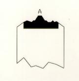
Prior to the muscle biopsy, four identical loops of thin cotton thread are fashioned to prep a single strip of tissue. Each loop forms a circle approximately 2 cm in diameter and is prepared by tightly encircling a cylindrical object, such as a test tube, with a piece of the thread, tying a secure knot, and clipping the thread ends close to the knot. Two loops are interlaced to form an open square knot (see Figure 1). This process is repeated with the second loop pair. The two paired loops will be used to gently stretch a single muscle specimen.
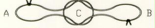
(Figure 1. Interlaced 2 cm diameter thin cotton thread loop pair forming an open square knot in the center. Note location of two knots with closely clipped thread ends. When the loops at A and B are pulled, the square knot will tighten on the end of the muscle strip inserted at C.)
One hole of a 2-hole stopper (to fit a 15 cm long test tube which will eventually be filled with the appropriate, cooled fixative) supports a tight-fitting glass rod with a recurved end which nearly reaches the bottom of the test tube when the stopper is in place (see Figure 2). The other end of the rod should extend about 5 cm above the stopper. A 20 cm length of thread extends through the second hole in the stopper and is tied to a thin, small rubber band to which is attached a small stainless steel hook made from a thin piece of wire.
If it is possible to confer with the surgeon before the biopsy, it is best to request and obtain a tissue specimen greater than 1 cm in length cut parallel to the muscle fibers and about 1/4 cm in diameter. Working quickly, under a dissecting microscope, elongate strips of the best material are cut parallel to the fibers using one or two new single-edge razors, while working on a sheet of dental wax. The strips should be less than 2 mm in diameter and trimmed so that their edges clearly define the orientation of the fibers and will allow tissue blocks cut from the specimen to lie flat during embedding. If desired, several strips may be prepped from the same specimen at this time using duplicate fixation devices.
To mount a specimen, one end of the strip of tissue is inserted in the open square knot of a loop pair and held securely by pulling on the distal portions of the loops. The free ends of the loops are hooked onto the recurved end of the glass rod. The other end of the tissue strip is similarly secured by the second loop pair which are attached to the hook at the end of the thread.
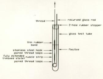
(Figure 2. Diagram showing 15 cm long test tube containing a fixative and plugged with a 2-hole rubber stopper. A tight-fitting glass rod is inserted in one hole and terminates in a recurve. A thread is inserted in the other hole and supports a thin, small rubber band to which is attached a small metal hook. The hook runs through a loop pair attached to the top of the muscle strip. The lower loop pair connects the bottom of the muscle strip to the glass rod recurve. Before the tissue is inserted into the fixative, the top of the glass rod and adjacent thread are held between thumb and forefinger. The top of the thread is pulled to fully extend the muscle strip to the relaxed state without damage to the muscle.)
Just before fixation, the upper ends of the thread and glass rod are held between thumb and forefinger and the thread is pulled until the strip of muscle, the loops and the rubber band become straight. Due to their design, the loop pairs tend to orthogonally stretch the muscle fibers. As explained in Figure 3, the muscle strip initially straightens but will still be in the contracted state. With further stretching, the muscle will extend fully into the relaxed state but will not be damaged since the rubber band will be first seen to extend and relieve any excessive stress on the muscle fibers. It is suggested that this procedure first be practiced on non-essential tissue. Sterile conditions should be employed for the safe handling of diseased tissue.
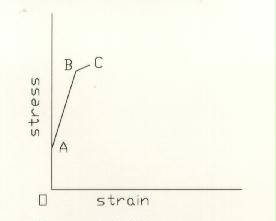
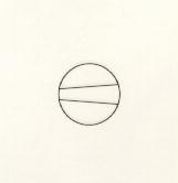
(Figure 3. Stress-strain diagram showing conditions relating to proper extension of muscle prior to fixation. As the upper end of the thread is pulled, it, the rubber band, the loop pairs, and muscle strip become straight. This is represented by the vertical line from the origin to point A. The line from point A to point B represents the contracted muscle strip extending to the relaxed state. With slightly more tension, the rubber band extends without damage to the muscle. At this point (C), the muscle is plunged into the fixative.)
At this point, the tissue is plunged into the fixative of choice and held in the extended condition for at least one minute until the tissue becomes sufficiently fixed to inhibit contraction if the thread is released. After the appropriate fixation procedure (often glutaraldehyde followed by osmium tetroxide), the tissue strip is rinsed in 30% ethanol and cut into at least six pieces with a #15 scalpel for cross and longitudinal sectioning. The pieces are then passed through a graded series of alcohol followed, usually, by infiltration with propylene oxide, propylene oxide/plastic, and plastic-embedded1.
It should be noted that the literature does contain articles devoted to procedures for overcoming the problems of fiber contraction and subsequent gross distortion of tissue, but the technique described here is simple, adequate, and specifically designed for the thin strip of tissue required for complete osmium tetroxide fixation for electron microscopy. Non-sterile materials may be used. An additional feature of this technique is that it allows the fibers of a specimen to be either merely straightened but left contracted (the usual condition after excision), or partially or completely extended (relaxed) before prepping and study. That is, prior to fixation, viable muscle in the device described here is able to completely contract and extend several times as tension on the rubber band is slightly varied.
Oriented Embedding
Use of lozenge-shaped silicon rubber molds of a type which produces optically-flat castings2 to orient tissue blocks for longitudinal and cross-sectioning is recommended. Normally, orienting the tissue structure to the long edges of the castings with a needle is usually only approximate, but this is not critical at this point. Covering the slightly overfilled wells with a sheet of Parafilm, prior to polymerization, causes the upper surfaces of the castings to be at the same level as the top of the mold after polymerization of the plastic. Before polymerization, bubbles in the molds may be removed by piercing the Parafilm with a new syringe needle. This technique results in parallel-sided castings which are well-gripped by the vise-type microtome chuck.
Oriented Tissue Block Exposure
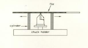
The optically flat surfaces of these castings (as compared to use of gelatin capsules) also allow relatively precise orientation of the tissue structure to the desired plane of sectioning if the chuck holder (specimen trimming block) is held sideways in a simple support and the embedment is viewed through a window (notch) cut in the top of a right cylinder resting against the chuck holder. The tissue block is viewed under a dissecting microscope at a magnification of 90X, which is sufficient for precise alignment. The tissue block is aligned to the edge of a microscope slide which is being held against the chuck holder2. The slide edge also represents the level at which the tissue block is to be transected and exposed for sectioning.
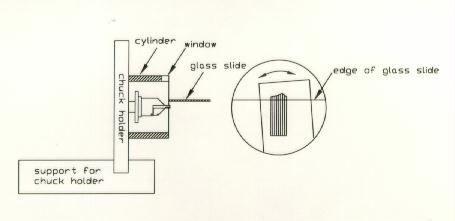
(Figure 4. Side view of chuck holder tilted 90 degrees and held in a notched support on stage of a dissecting microscope. A plastic cylinder is pressed against the chuck holder and a glass microscope slide pressed against the top of the cylinder. By moving the casting in or out and swinging it left or right, the tissue block is precisely oriented so that it the muscle fibers protrude beyond and are (in this case) perpendicular to the edge of the glass slide. Alignment is seen in the circle on the right which depicts the magnified field of view in the dissecting microscope permitted by the window cut in the top of the cylinder. Note that the sides of the tissue block are perpendicular to the slide edge, but happen, as is usually the case, to not be parallel to the edges of the casting. Also, the end of the tissue block is often not square to the fiber length. Other embedded blocks may be similarly transected for sections parallel to the fiber length.) Other embedded blocks may be similarly transected for sections parallel to the fiber length.
Transectioning is accomplished by placing a coarse file (with protective tape) on top of the plastic cylinder as it rests on the chuck stand and sliding the cylinder and file (as a unit) across the surface of the stand (Figure 5). The action of the file’s edge gently removes extraneous plastic and tissue to the desired plane of sectioning. The coarse file is replaced by a finer, taped file which imparts a relatively smooth surface to the embedment. Dust particles produced can be vacuumed away at this time. The transection surface is similarly further polished by burnishing it with a fine nylon cloth epoxied to a glass plate. The smooth surface produced permits accurate alignment of the tissue block face to the plane of sectioning of the glass knife on the ultramicrotome3 (see below) after the clear plastic, peripheral to the tissue block face, has been trimmed away. A few cycles of the ultramicrotome will face the entire block face prior to cutting 1 um thick sections at that predetermined level in the block and with the desired orientation.
(Figure 5. Side view of chuck holder shown in Figure 4. The plastic cylinder rests on the chuck holder and supports a coarse file. Sliding the cylinder and file as a unit across the chuck holder’s base reduces the casting to the level determined by the edge of the glass slide as described in Figure 4. A fine file followed by a plate glass with fine nylon cloth epoxied to it further smooths and burnishes the worked surface so that it is planar and reflective during alignment to the plane of sectioning on the ultramicrotome. Prior to sectioning, the empty plastic surrounding the tissue block is removed with a razor. Strips of tape on the files protect the cylinder.)
Block Face Alignment
Since the tissue block has been exposed and a reflective planar surface imparted, which is either parallel or at right angles to the muscle fibers, it is important to align that surface to the plane of sectioning. This is facilitated by removing the metal detent plate just below the front surface of the glass knife and inserting snug-fitting wooden dowels into the two bolt holes. A small first-surface mirror, in contact with the knife face, is glued to the dowels.
In use, light coming from the ultramicrotome lamp reflects from the mirror to the knife face, to the block face, and to the dissecting scope (figure 6). The microtomist observes a reflection of the knife face (on the block face) as a bright band
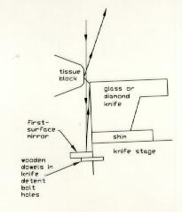
(Figure 6. Diagram showing first-surface mirror glued to two wooden dowels inserted in bolt holes formerly used to retain knife detent plate. Light from the lamp reflects from the mirror to the knife face, to the block face, and then to the dissecting microscope. The observer sees a reflection (on the block face) of the knife face as a bright band between the knife edge and its reflection.)
between the knife edge and its reflection. By rotating the knife stage about a vertical axis, moving the knife left or right and in and out, swinging the specimen chuck about a horizontal axis, and rotating the block face about its perpendicular axis, the bright band can be caused to remain constant in width as the block face is moved up and down in front of the knife edge. A vernier scale (Figure 7), drawn on acetate film and glued to the specimen chuck on the microtome arm, aids in very small corrections in tilting the block face. Moving the knife forward until the bright band just disappears brings the knife edge to the block face. Tilting the dissecting microscope to a near vertical orientation and frequent alignment of the lamp to increase brightness of the band facilitate this operation.
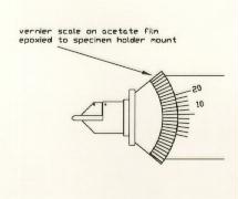
(Figure 7. Vernier scale drawn on acetate film and epoxied to chuck on microtome arm allowing precise control of block face tilt with regard to the plane of sectioning.)
While this alignment procedure seems overly long, it has to be performed virtually only one time. Once the lamp, mirror, and microscope are in position from a prior alignment, all that is required to align another specimen is to produce a good reflection of the knife edge by rotating and tilting the block face as it is being observed. Alignment is accurate to approximately one degree. Rotation of the knife edge to the plane of sectioning produces a bright band of even width. Alignment is fast and precise and the brightness of the band allows the knife to be brought within a few microns of the block face3.
Thick Sectioning
Use of a box-like device (superstage) which sits on the knife stage of the ultramicrotome4 (Figure 8) acts as a hand rest to facilitate block face alignment and section handling. It also allows a cluster of thick sections to be adroitly expanded while working at the ultramicrotome and then positioned at a fixed location on a glass slide so that the clusters in a series of slides will always be centered in the field of view in the light microscope without excessive use of the mechanical stage controls. Additionally, the last section cut from the block face is placed a small distance from the cluster to indicate what structures most likely remain in the block face. Recording the slide/block face number and the stage vernier coordinates for an area of interest observed on the last section allows the microtomist, at a convenient time, to shape the minute block face with that area centered on it by trimming away surrounding material. This process is described below. If desired, so that an interesting block may be recut for another series of thick sections, the level of the surrounding tissue should only be slightly reduced and not be completely removed. This leaves the small block face for ultra microtomy mesa-like above the reserved tissue (see Figure 9).
(Figure 8. Exploded view of components required to produce a superstage which rests upon the knife stage of the Porter-Blum MT-2 ultramicrotome. The superstage acts as a hand rest and tool micromanipulator, it's detents permit thick section clusters to be placed at the same location on slides, and it eliminates air currents which can disturb ultrathin sections as they float on the knife boat.)
(Figure 9. Side view of tissue block from which thick sections have been cut and which has been retrimmed for ultrathin sectioning of block face at A. Note that most of the tissue block has been conserved for subsequent thick and ultrathin sectioning.)
Locating Areas of Interest for TEM
Locating areas of interest on the block face for ultrathin sectioning is a precise but simple task performed under a dissecting microscope. Exposing the block face to xylene vapors (or those from another, suitable solvent), as it is viewed under grazing reflected light, causes a sort of bas-relief of the tissue structure at the block face to appear5. This is caused by a slight, temporary, absorption of the solvent in the block face and consequent swelling of the plastic. Fat globules and large, tissue-free areas swell the most, while capillary lumens, extra-cellular space and fibers swell progressively less. A comparison of the last section cut from the block face and the block face itself allows any area of interest in the section to be visually located on the block face. These areas can include regions as small as a portion of a single muscle fiber (cell), a cluster of mitochondria or several nuclei to be isolated for ultrathin sectioning. Only once in hundreds of trimmings was it impossible to locate an area of interest on a block face due to a symmetry problem. Trimming the outline of the block face prior to thick sectioning so that it exhibits no symmetry obviates even this unlikely problem. This is simply performed by trimming away one corner of an otherwise rectangular block face. Additionally, the compression artifact in the section is integrated across the block face and thereby mentally eliminated by the microtomist as the area of interest is isolated.
A specially-designed, hand-made reticle6 cut from a cover glass to fit the ocular of the dissecting microscope permits the area of interest to become centered on what will become the block face from which ultrathin sections are to be cut. It allows the block face to be trimmed to a routine, acceptable size and trapezoidal shape (Figure 10) if a fixed magnification under the dissecting microscope (approximately 90X) is always employed.
(Figure 10. Hand-made ocular reticle cut from a cover slip. It is used in a dissecting microscope to center an area of interest seen in a thick section on the much smaller, but standardized, block face used for ultra-thin sections. Non-parallel lines define long edges of the block face trimmed with a razor.)
Ultra-thin Sectioning
A second trimming device which I call a trim-align block6 is a square block of 1 cm thick plate-glass, just narrow enough to fit into a spare knife holder. It is produced on a glass knife maker. Prior to its installation, the horizontal cross-hair in an ocular of the binocular microscope is aligned to the diamond knife edge. One of the four short edges of the glass block is selected for use if it is parallel to the cross-hair. The knife may have to be shimmed to be approximately at the same height as the glass edge. When a suitable glass block is produced, it can be used for years.
The trim-align block permits the block face to first be aligned to the plane of sectioning (as previously described). The trim-align block then allows the narrow top and wider bottom of the trapezoid to be lightly trimmed with a razor (Figure 11) so that these edges are parallel to each other and eventually to the edge of the diamond knife during sectioning. These procedures cause each section, as it is cut, to be freed of the knife edge and results in the formation of very straight ribbons of sections. A technique for safely and efficiently cleaning diamond knife edges7 before and during sectioning is also helpful to section production.

(Figure 11. Side view of trim-align block and single-edge razor blade sliding down to lightly trim bottom edge of a tissue block prior to ultrathin sectioning. The trim-align block is a square block of plate glass the forward corner (short edge) of which has been selected because it has the same orientation as the cutting edge of the diamond knife and occupies the same location. The block face and glass block have first been aligned to the plane of sectioning using reflections from the mirror. Note the upper edge of the block face has already been trimmed with the glass block tilted in the opposite direction. The top and bottom edges of the trimmed block face are parallel to each other and will be parallel to the diamond knife edge. As a consequence, straight ribbons will be routinely cut.)
The superstage, previously mentioned4, also acts as a very efficient wind current barrier allowing ultrathin sections to be cut and remain motionless at the surface of the trough. Air-conditioning currents in the lab often cause the sections to spin uncontrollably on the water surface. In addition, by using the slot in the top of the superstage as a steadying guide for forceps tines, rafts of sections can be readily assembled and the grid precisely brought into contact with them. The slot (a few mm above the water surface) allows the instruments to function as micromanipulators (Figure 12).
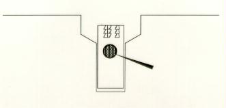
(Figure 12. A pair of interlocking ultrathin section ribbons (left) at the knife edge. Alternating ribbon directions generates 100% grid coverage based on straight ribbons of trapezoid-shaped sections routinely produced by techniques outlined here. The third ribbon on the right will extend the coverage. Forceps tines resting on right-hand edge of slot in superstage permit micromanipulation of grid down to the sections.)
Since ribbons produced with these techniques are routinely remarkably straight, the trapezoid geometry of the sections initially provides for 100% coverage of grid openings if the direction of short adjacent ribbons is alternated (Figure 12). However, ribbon edges in contact with adjacent ribbon edges may sag and separate slightly as they cross grid openings. It should be noted that to facilitate adhesion to the grid of a 100% section-coverage raft, it is important to press the raft into the water surface with a petroleum ether-cleaned grid and condense breath moisture onto the sections.
Structure Confirmation
When sufficient sections have been cut and placed on grids, a final, thicker section may be cut for staining on a microscope slide and examined under the light microscope. If this section still exhibits the same area of interest seen in the last, large, micron-thick section, it indicates that the ultrathin sections must also carry the same structures. This thick section may also be studied with the light microscope sitting on the work surface of the electron microscope. One can then simultaneously compare light and electron microscope views of the same structures since both the light and electron microscope sections are obviously of the same size, shape and material.
Staining Grids
A staining device (Figure 13), comprised of a 1 ml tuberculin syringe holding a very small Millipore filter and support pad cut with a number 1 cork borer is described8. It allows approximately 20 grids, firmly held on a slotted rod, to be stained (and later washed) under identical conditions using a minimum (<1 ml) of stain which has been filtered immediately prior to its contact with the grids. Using the plunger, stain is drawn into the syringe barrel to cover the grids. After staining, the grids are minimally brought into contact with freshly boiled and cooled (degassed), filtered wash water. This is performed by removing the needle containing the filters, and plunging the end of the syringe into wash water. The plunger is removed (causing wash water to rise and displace the stain) and immediately replaced with a loose-fitting cylinder attached by tubing to a vacuum bottle to draw more water past the grids. After washing, air is then briefly drawn through the syringe, the barrel inverted, the grid holder extracted and the grids instantly dried by dashing the grid holder and grids against paper toweling. Grids are inserted and removed using a specially constructed device which bends the slotted bar.
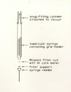
(Figure 13. Diagram showing tuberculin syringe, filter, filter support pad, needle, grid holder and vacuum wash device. The sections are directly exposed to filtered stain followed uninterruptedly by wash water. Dashing the washed grid holder (and grids) onto paper toweling immediately dries the grids.)
Temporary Storage of Grids
The grids cut from a single block face can be gently but firmly held fixed in position at the edge of the adhesive field of an inverted Post-it® pad (100 sheets, 76.2 X 76.2 mm, 3M Corp., St. Paul, MN) under a dissecting microscope, which sits in the cover of a square, plastic petri dish (Figure 14). The grids are identified by a number directly written on the pad and categorized as to whether or not they are unstained, stained, or stained and examined9. These grids may then be permanently stored in a grid box at a later time and a new page exposed on the pad.
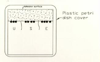
(Figure 14. Sketch of inverted, square Post-It® pad (grid-pad) sitting in the cover of a square plastic petri dish. Section-bearing grids lightly adhere to the pad at the edge of the exposed adhesive strip. Grids are immobilized and grouped according to whether they are unstained (U), stained (S) or examined (E). Descriptive notes, including specimen number, can also be conveniently written on the adjacent pad surface. The dish bottom acts as a cover. Using an inverted dish allows easier access of forceps to grids.)
CONCLUSIONS
While the techniques described here were devised to adroitly handle the linear structure, and make available for detailed study the often infrequent, random lesions presented by skeletal muscle, all of what is presented here, after the section on fixation, can be utilized for other types of tissue prepped for TEM. Versions of some of the devices may be commercially available, but those described here can be readily built in the laboratory at little or no cost and are able to compensate, where applicable, for the non-alignment of the tissue structure to the casting. That is, the block face does not have to be at right angles to the axis of the casting. Alignment techniques described here also apply to ball-and-socket collet-type specimen holders.
Much of what is presented here should have been sufficiently described to be understandable. However, the original, referenced articles are more detailed and may be consulted.
If you have any questions, or comments, please send email to: [email protected].
You are visitor number:
Cited References
1. Gorycki, M. A. 1978. Mixing embedding media in plastic bags. Stain Technology, 53: 116-118.
2. Gorycki, M. A. 1983. Optimized transection: A prelude to oriented sectioning. Stain Technology, 58: 219-225.
3. Gorycki, M. A. 1977. Simple and rapid block face alignment methods for the ultramicrotome. Stain Technology, 52: 255-260.
4. Gorycki, M. A. 1989. The ultramicrotome superstage: A versatile aid for section manipulation. Stain Technology, 64: 197-199.
5. Gorycki, M. A. 1966. Oriented embedding of biological materials and accurate localization for ultrathin sectioning. Stain Technology 41: 37-42.
6. Gorycki, M. A., 1978. Methods for precisely trimming block faces for ultra microtomy. Stain Technology, 53, pp. 63-66.
7. Gorycki, M. A. and Oberc, M. A. 1978. Cleaning diamond knives before and during sectioning. Stain Technology, 53: 51-53.
8. Gorycki, M. A. 1978. An efficient staining method for ultrathin sections. Stain Technology, 53: 11-15.
9. Gorycki, M. A. 1992. A simple method for handling grids. Biotechnic & Histochemistry, 67: 313-314.