Computer Graphics II
Project 1
Recursive Ray Tracing
Main Features :
1.Primitive Objects Implemented :
Cuboid, Sphere, Rectangle, Polygon(triangle), Infinite plane, General quadrics, Polyhedrons and their affine transformations.
2.Illumination :
All three components implemented i.e. Diffuse, Specular and Ambient.
3.Constructive Solid Geometry:
Implemented CSG-tree using union, intersection and set-difference operations on sets of intervals.
4.Implemented Multiple Light Source
6.Implemented Shadows
5.Implemented Reflection and Refraction with user specified refractive index
7.Implemented 'program-generated' as well as 'bitmap image' texture mapping on 'finite' objects:
Some of the textures are generated using some simple procedures and some are in the form of bitmap that are loaded into the program in runtime.
The textures are mapped using "Intermediate Surface Technique" by first mapping the texture to a spherical or cylindrical surface which is parameterized in two usual variables 'theta' and 'phi', the angle of rotation and the angle of elevation of the point vector of a point on the surface.
8.Implemented program-generated bump mapping on sphere:
The bump map is generated by a procedure and mapped to object in the same way as the texture.
9.Implemented anti-aliasing using supersampling:
Supersampling is done only with the initial rays from the viewport.Each pixel is divided into a square grid say 3 by 3 grid and 9 rays are casted passing through the centers of each of the 9 grid elements and the results are averaged out to give the final color of the pixel.
One can also choose to add 'jitter' by instead of taking the sample point at the center of the grid squares, each point is selected randomly inside each grid square with uniform probability in both the cartesian directions.
10.Implemented optimization scheme:
Octree is implemented for speed-up of the computations.Each cell in the octree is subdivided until it contain no more than say 3 objects.Each node of the octree had the information of array indices of the objects it intersects.
The octree is set up initially by finding the intersection of each object with each of the initial cell, and then during subdivision by finding intersection of the objects, a node intersects, with its child cells.
While ray tracing we traverse the tree to find the leaf node to which the ray is incident to and find the intersection with all the object that node contains.If the intersection point is inside the cell, it's fine, otherwise make the starting point of the ray just 'epsilon' ahead of the point it leaves the cell and do the computation again to get the actual intersection.
Result: Rendered 27 texture-mapped and bump-mapped spheres in the configuration of a cube with and without optimization. The time taken were:
With octree-optimization : ~20 seconds
Without octree-optimization : ~40 seconds
11.Implemented Distributed ray tracing:
Effects Generated:
1.Soft shadows
2.Blurred reflections
3.Blurred refractions
4.Depth of Field
By shooting multiple rays as in case of anti-aliasing but here the grid is of a solid angle instead of a pixel and the movement in X and Y directions before corresponds to movement in Theta and Phi in a certain range.The rays which are near to the actual ray are given more weightage but sum of all the weights is 1.To implement jittering some uniformly random dislocations are given to each of the rays in the two directions.Using this Soft-Shadows, Blurred-Reflections and Blurred-Refractions are implemented.
For Depth of Field(Ref. "Distributed Ray Tracing" by Cook in Siggraph'84) while casting each initial ray, a lens is implemented whose center passes through the ray.The distance of the lens from the viewport is calculated given the focal length of the lens and the distance of the plane to focus on from the viewport.Given the aperture of the lens we cast a number of rays starting from the lens at distributed points which intersect the actual ray at the point when the actual ray intersects the plane to be focussed.
12.Implemented Adaptive Recursion Depth Control:
For controlling whether we need to cast the refracted and( or ) reflected rays at any depth, we find the proportion by which the ray to be casted will affect the color of the pixel on screen, this can be done by multiplying all the coefficients which would be multiplied to the color of the ray to be casted, and checking whether it is less than some threshold in which case we don't cast the ray. And also there is an upper limit to the depth.
12.Scene File:
A scene file having all the information about the scene to be rendered is given as a command line argument while executing the code. The file format is described in the link below:-
By-
Abhishek Nagar(2001057)
(Mathematics and Computing Deptt. )
I.I.T. Delhi, India
Under the guidance of-
Prof. Prem Kalra
(Computer Science and Engineering Deptt.)
I.I.T. Delhi, India
HERE ARE CERTAIN IMAGES DEPICTING SOME OF THE FEATURES
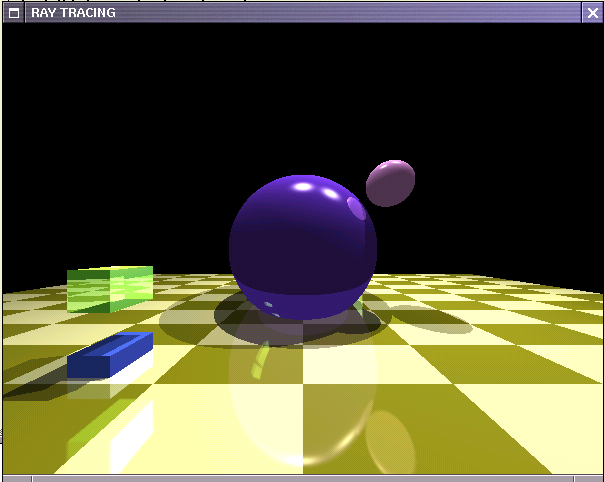
The image above depicts refraction from the sphere

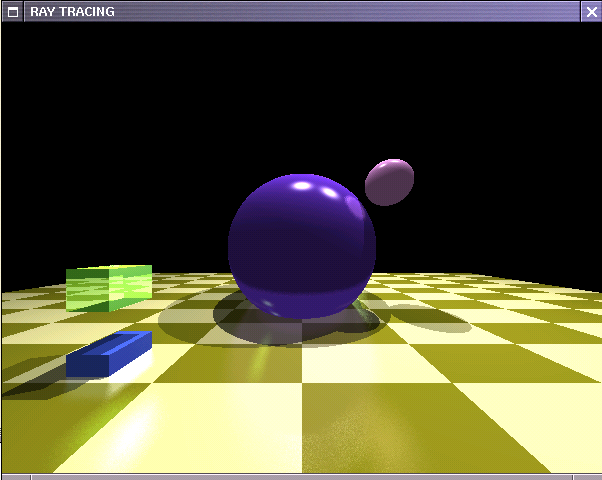
This image depicts the effect of anti-aliasing using supersampling.

This image depicts the effect of supersampling with jittering
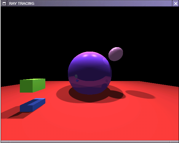
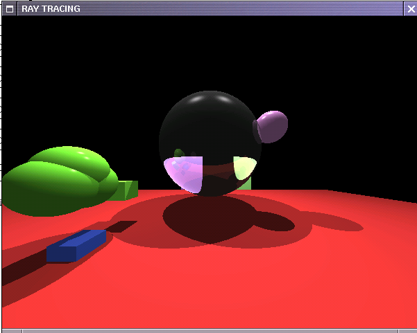
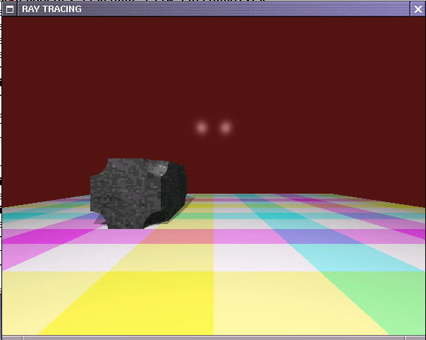
This image depicts soft shadows using distributed ray tracing.
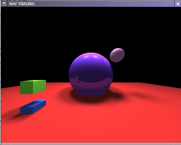
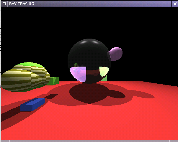
This image depicts soft shadows using distributed ray tracing and jittering.

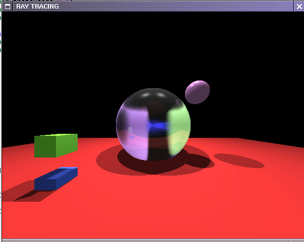
This image depicts blurred refractions using distributed ray tracing.
This image depicts blurred refractions using distributed ray tracing and jittering.
This image depicts blurred reflections using distributed ray tracing.
This image depicts blurred reflections using distributed ray tracing and jittering.
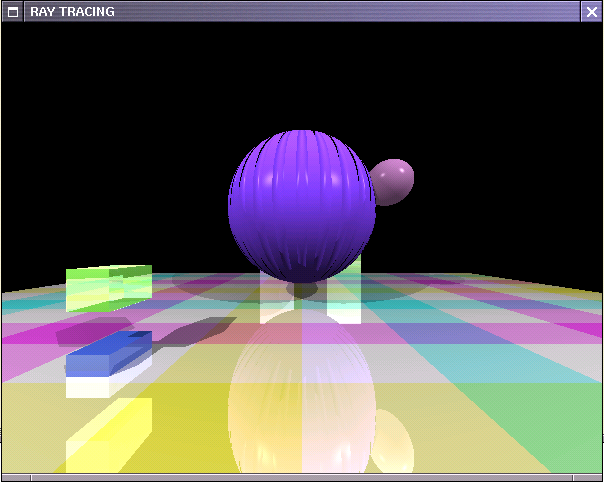
This image depicts bump mapping on a sphere
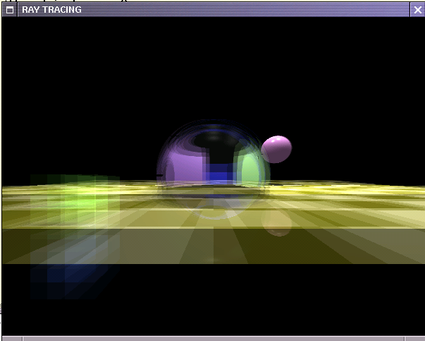
This image depicts "depth of field" effect using distributed ray tracing

This image depicts "depth of field" effect using distributed ray tracing along with jittering
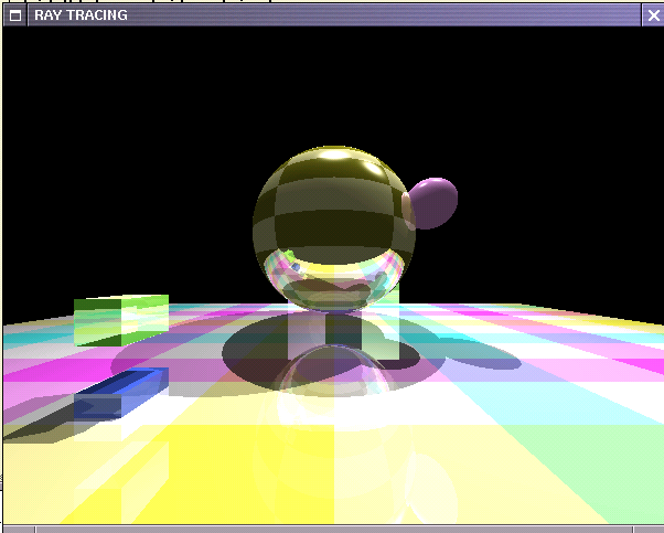
This image depicts texture mapping on plane as well as on sphere
This image depicts object made by union of three spheres using Constructive Solid Geometry tree

This image depicts object made by intersection of three spheres using CSG tree
This image depicts texture mapping on a CSG object
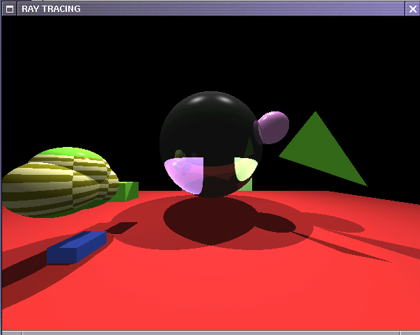
This image depicts a triangular planar surface
This image depicts a figure made by difference of eight spheres from a cuboid at its eight corners using Constructive Solid Geometry

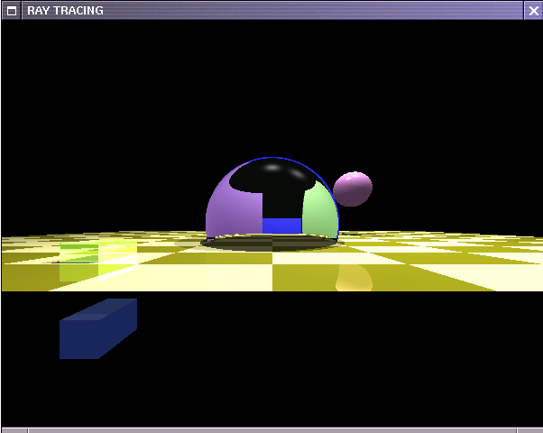
This image depicts a cup made using general quadrics(paraboloid) and their union with a sphere and a translucent tetrahedron