| Tualatin-izing your
ABIT ZM-6
| By:
Haut^Karl |
Tuesday,
October 29, 2002
Updated Sunday, November
10, 2002 |
My motherboard is not Slot1,
it's socket370. I don't have a slocket to mod
so how can I put a Tualatin processor in my
Celeron-only motherboard? Most slotkets took
care of the pins required for Pentium3 operation
which meant the standard '3 pin+bridge' mod
would be sufficient. However, a Celeron-only,
socket370 motherboard is very similar to modding
a generic Celeron-only
slotket but without the slotket. This new
mod is so similar, we can reuse much of the
info contained in that article.
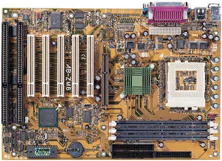
Picture 1
Step 1:
RESET pins
As you may already
be aware, the RESET# pin moved when the Pentium3
was designed and RESET2# was added to the Tualatin
design. RESET2#, pin AJ3, was added by Intel
to prevent Tualatin CPUs from operating with
non-i815E stepping B chipsets so we will merely
insulate and forget about it. But we must bridge
the old location of RESET#, pin X4, to the new
Pentium3/Tualatin RESET# pin as depicted in
Diagram 1 with a Red
line.
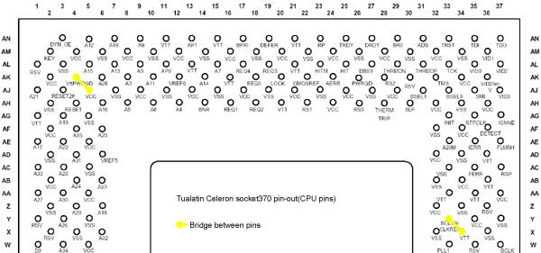
Diagram
1

We accomplished
this using some thin wire and a soldering iron.
Conductive paint may work but you have a lot
of pins to avoid. Try painting the pathway and
unwanted pins, first, with a non-conductive
paint to avoid errors. Then make your connection
with the conductive paint on top of the other
paint.
Picture
2

Step 2: Open
your ZIF socket
Remove the sliding part of the
ZIF socket with a small screw driver(Refer to
this article
for help). Use a black pen and blacken-in the
two indexed corners so you don't get the pins
mixed up. Mark the following pins on the ZIF
socket with black: AN3, AM2, AG1, AK4, AJ3,
X4, X34 and Y33. Be careful since the pin numbers
are reversed when looking down on the socket.
If you look at the back of the motherboard,
the pins of the ZIF *now* correspond to the
pin numbering in the Intel pdfs.
We are going to use sticky tape
to insulate these pins. Use your judgement to
figure out how big the piece of sticky tape
needs to be to cover the contact for each pin.
Don't worry if the tape is too long. You can
trim it down with a sharp razor blade.
After you insulate all 8 pins,
you can reassemble the socket.
Step 3:
Bridges Galore
The quick an easy
method of Tualatinizing your ZM-6 is to power
your Vtt pins using adjacent Vcc supply pins.
If you would like to supply your Vtt pins with
1.5v, then check out the note below.
Check the following
ZIF socket pins with a voltmeter for connectivity
to Vss or Vcc: AN11, AN15, AN21, AL13, AL21,
AK16, AH20, AA33, AA35, U35, U37, S33, S37,
G35, G37, E23. If these pins are not connected
at all, we need to bridge Vcc to them(Vtt 1.25v
would be better, but we have to generate the
1.25v ourselves which is a mod we plan to do
in the future). For our motherboard we had to
connect(refer to Diagram 1)
all of the above pins to nearby Vcc pins.
Note:
We found the ZM-6 to be particularly good at
overclocking the Tualatin Celeron so we devised
a mod to our first mod to gain, hopefully, longetivity!
We put together a method of powering all the
Vtt planes with 1.5v from a single source. There
is no reason why someone couldn't do a simple
resistor network and reduce this single 1.5v
source to 1.25v, but that's another story. If
we substitute Vtt into the above paragraph as
the source of current, we get our new mod.
Check the following
pins on the ZIF socket with a voltmeter for
connectivity to Vss or Vcc: AN11, AN15, AN21,
AL13, AL21, AK16, AH20, AA33, AA35, U35, U37,
S33, S37, G35, G37, E23. If these pins are not
connected at all, we need to bridge them to
1.5v. For our motherboard we had to connect(refer
to Diagram 2) all of the above
pins to a nearby 1.5v pin(AD36).
Diagram
2

We used a combination of conductive
paint for the short runs and solder & wire
for the longer runs. Yellow, non-conductive
paint was used to insulate the pathway before
we applied the conductive paint. Most non-metallic
hobby paint will suffice. It made the mod much
easier.
Picture 3

Step 4: VID
pins
(Moved and expanded on, here)
Step 5:
CPU Bridges
Diagram
3
Grab your conductive
paint and make the bridge from AK4 to AJ5(Check
this article
for optional AK4 bridges). Also make a seperate
bridge from Y33 to X34. X34 is internally powered
by the Vtt plane.
Finishing
Step: Installation
Insert your Tualatin
processor into your motherboard, remove the
thermal pad & adhesive from the heatsink,
apply some thermal grease, and install your
heatsink. Clear the CMOS, then power-up. Go
into the BIOS and set the FSB to 100, Multiplier
to 9x, AGP to 2/3, Speed Error Hold disabled,
and Voltage should be 1.45v. We were able to
get our Celeron 1.2 up to 1.6 GHz 133 FSB at
1.65v which we set in the BIOS.
Here's the Intel
Checklist that was very helpful.
Troubleshooting:
If you need some help from fellow
modders, try any of the forums below.
The LunchBox Forums
Forum Thread at Overclockers.com:
"running
Tualatin on CuMine MB w/o Powerleap"
Forum Thread at MadOnion.com:
"Tualatin
on a BX Mobo works. No Adaptor Required"
|
