 Question:
Question:
When I want to overhaul the engine, gearbox etc, do I need a lot of special tools?
Answer:
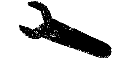
It all depends on your workshop. It will be very helpfull if you have a lath. You can make the nicest tools with a lath and a standing drill. But you can also improvise lots of tools with rough lumps of steel and welding equipment. Most gears and bearings have a tight pressfit, so you need very sturdy tools. You should buy an exhaustnut wrench. There are two types, for the finned exhaust nuts of the R69, R50S and R69S. And the nut to remove the flat nuts, with little holes in the side on the R50 and R60. Both are not extremely expensive, but invaluable. Another thing is a heating device. A blowtorch is too hot. It will melt the aluminium castings. I always use a large electrical cooking plate.
Ed Korn has an excelent array of tools for sale for these purposes. Look at his webpage.
Some tools for engine (dis)assembly:
All sizes in milimeter
- To release the clutch spring pressure, you need two or better three M8x1 fine threaded screws with nuts and some 40mm long. The cardan housing is fastened to the rearwheel casting with studs that have M8x1 and normal M8 thread. When you use these, you can srew the fine thread in the clutch and use the course thread to release the spring.
- Clutch center tool:
- To pull the dynamo and the magnet from the crankshaft and the camshaft, use a strong steel stift of 60x6mm. This should be strong, because, when it bends, you have a big problem. Put the stift in the appropriate opening and push with an M8 bolt.
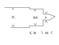
- Universal puller plate 200x80x8 with one hole the middle of 8.5 mm and two slots of 8.5x45 on both sides of the hole with 15mm in between:
To be used together with M6 and M8 studs to pull of the large timing gear housing on front of the engine. And together with a steel bush of 48 outer diameter and 35.5 inner and some 100 long (you should take some messurements to see how precise this is, but you should get both ends true parallel), and a M8 stud to press the front crankshaft bearing and the crankshaft gearwheel.
- The flywheel puller
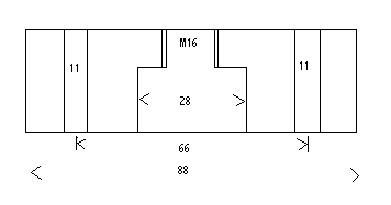
You need an M16 bolt to press and two M10x1 fine threaded bolts to attach the puller to the flywheel, which accomodates two threaded holes for this purpose. Also you must put a strong steel disk of 27 mm outer diameter between the M16 bolt and the crankshaft to protect the threads overhere. The front suspension units are fastened with M10x1 x48 bolts. A simplified version could consist of a piece of U profile, with a 18mm hole, and a M16 nut welded over this hole. When this nut is fixed, measure the place of the 11mm holes and drill them.
- The R69 and the R69S have a special rear crankshaft bearing. This bearing can cope with the flexing of the crankshaft, but during assembly it needs to be fixed in place. You really need a lath for this tool. Dimensions:
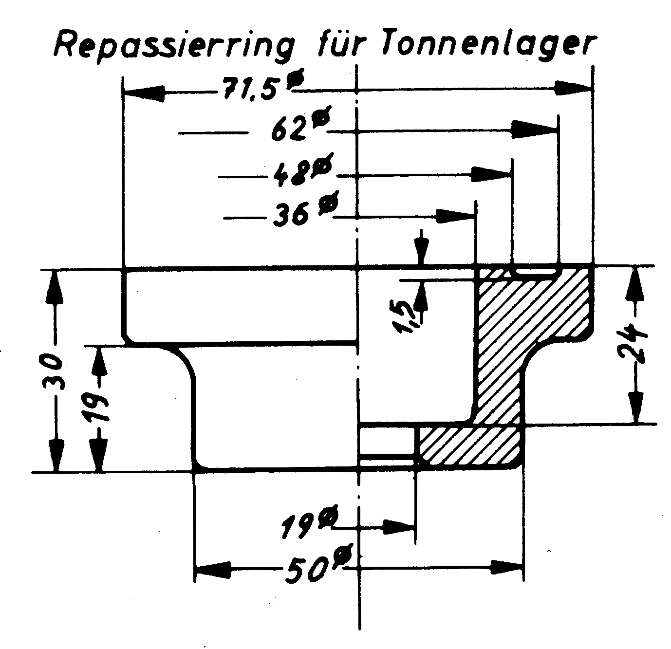
To be fitted with the large flywheel bolt.
- To fit the crankshaft in the rear bearing house you should use enough heat to let it slide in. But sometimes you have to use some extra force. Don't smash with a hammer on the front of the crankshaft, but you can use this trick: get an old flywheelnut (M18x1.5) and drill a hole in the middle with M8 thread. Together with a stud and the universal plate and some lumber, you can pull the crankshaft in to place. - You can remove the camshaft with the universal plate, two 70mm wooden bars and a M8 thread. Put the lumbers under the plate and pull the complete camshaft together with gearwheel and all the front bearings out. (The R69 is the only one with two frontbearings). The rear bearing can be pulled out with some hooks, and a rope, when the whole engine casting is being heated, to remove the crankshaft. For (dis)assembly of the camshaft wheels and bearings, you can also use the universal plate.
- Pulling the crankshaft gearwheel is done with a normal two arm puller. Maybe you must ground it down on some places to make it fit. Use a clamp to press the two arms together. Protect the crankshaft with a bolt. And don't forget to remove the seegerring on the pre '63 engines... J.C Whitney sells a "pitman arm puller" that has the right dimensions for this job.
- Mandril to remove the wheel bearings from the brake side:
- Key to remove the special big wheel nuts.

Make one 10 mm hole in the middle and place two 4 mm pins on 44 mm. For the pins, I used M5 bolts, turned down to 4 mm. With the remaining thread, you can attach them to the steel plate. The joke is, to put the steel plate with the pins on your wheel. Put an M10 stud though the 10mm hole and the wheel, and fix everything with some nuts and rings together. Now you can put a lot of force on this tool, without the risk of damaged keyholes.
- A setup to disassemble the front suspension units is easy to make. The goal is to reach the shock absorber arm with a 9 mm spanner. Make from plywood two plates one with a dimple to hold the underside of the unit in place, the other with a 58 mm hole to go over the upper aluminium part and on to the black cover. Now make some extra holes in the plywood for two long M6 studs alongside the suspension unit. You can press the unit together now, but most probably the upper aluminium part will be oxidized together with the black cover. So you must put a steel rod through the upper alu part, and attach it to the studs with some nuts, steel plates and wire. Now you can screw down the plywood with two nuts on the studs.