MEASUREMENTS
Since I am a curious guy, I wanted to know exactly how the BMW /2 magneto works. Here in the lab I have access to all kinds of measuring equipement, but it is impossible to drag the bike inside, hook it to an oscilloscope and start it up. Beside that I also wanted to take some measurements with the magneto rotating but the points disabled.
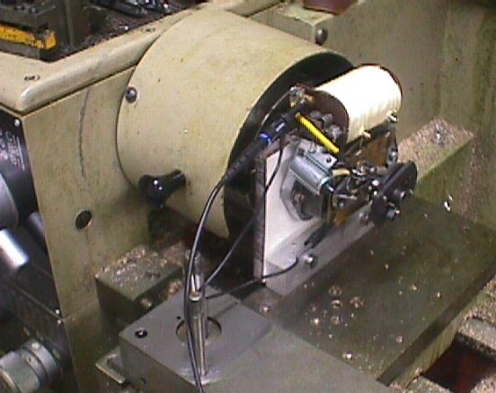
So I made a jig to mount the magneto in the lath. Now I could measure in the comfort of our workshop without being disturbed by angry managers. For them who don't know what an oscilloscope is, don't worry. It's just a machine to show nice graphs of electrical voltages. The graphs show voltage in the vertical direction. Time is in the horizontal direction.
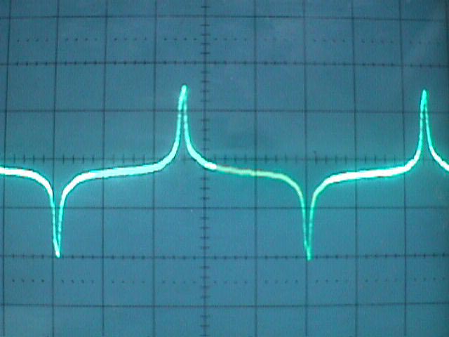
First I adjusted everything so I could see how the ignition pulses look like. With the lath spinning at 520 rpm I got this picture. The magnet is normally mounted to the camshaft which spins at half the speed of the crankshaft. So the 520 rpm's of the magnet are equall to 1040 crankshaft rpm's.
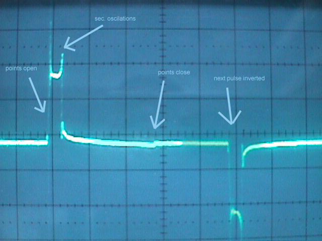
Horizontal 10 ms per division, Vertical 10 Volt per division
When the points open you see how the voltage shoots into the air and oscilates up an down in a very quick rythm. These are the primary oscillations. The voltage oscillates between the primairy coil and the capacitor. Then the voltage stays around 20 volt for a while until the spark extinguishes. At that moment the secondairy coil oscillates a couple of times. That is called secondairy oscillations. A small step is visible when the points close again, and the coil starts to magnetise again. You don't see the voltage rising much here, because the points are closed, thus a short circuit for the coil. Rest assured though that there is a lot of current flowing. The next pulse is inverted because now the magnets north and south pole have changed place.
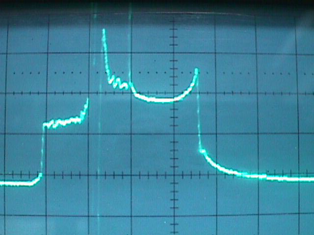
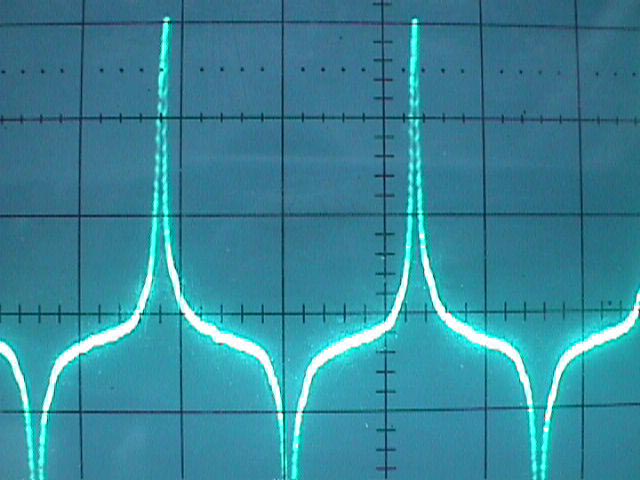
To be able to see the primairy and secondairy oscillations better, I took a new measurement with a magnified timescale.

Horizontal 1 ms per division, Vertical 10 Volt per division
At the far left you see how the voltage slowly rises a couple of volts. The current flowing through the primary coil and the capacitor is now so big that you get a visable voltage drop over the points. When the current is at its maximum, the points open. Due to the selfinduction you get such a big voltage spike that it doesn't fit on the screen. Between primairy coil and capacitor the voltage oscillates until it is damped out. After 5 ms you see a new oscillation . According to my textbooks that is the secondairy oscillation. When the spark extinguishes, the secondairy coil is still at several hundred volts. That voltage oscillates because there is no current path anymore. These oscillations are transformed back into the primairy coil.
For the record I also took a meassurement at 3000 rpm = 6000 rpm at the crank.

Horizontal 1ms per division, Vertical 10 Volt per division
You don't see a lot of difference. The spark is about just as wide.
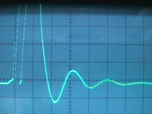
To show the importance of the capacitor I made a meassurement without capacitor. With sparks flying between the ignition points I got this picture at 520 rpm.
Horizontal 1 ms, Vertical 10 Volt.
When the points open, all the arcing between the points delays the spark more then a millisecond. At 520 rpm camshaft speed, the crank turns around at 1040 rpm. So 1 ms is a 6 degree delay. You can't see in this picture the difference between the first voltage spikes, but because the primairy oscillations are a lot less, I conclude that there is a lot less energy available for the spark.
Then I connected a 7 microF capacitor over the points instead of the normal 0.25 microF capacitor. I got these results:
Horizontal 1 ms per division, vertical 10 Volt per division.
What I think is the worst for the spark in this picture, is that the rising slope of the oscilations is much slower then normal. Too much energy is absorbed into the capacitor instead of in the primairy coil. The system is not very critical for the capacitance though. When I connected two 0.25 microF capacitors parallel (creating 0.5 microF), I couldn't see any difference.
I have detected a fault in my own magneto though. When I first meassured, I found a short delay when the points opened, together with a lot of sparking between the ignition points. In my case there was a broken soldering at the connection of primary coil and capacitor. That creates a series resistance between capacitor and coil, with the same result as a weak capacitor.
To conclude this series of meassurements, I disconnected the coil from the ignition points. The idea was to get an impression of how the magnet puts energy into the coil. When the current can't flow through the points, the voltage will rise according to the energy that is stored in the coil. I made measurements at two speeds, 520 and 1000 rpm.
 Horizontal 20 ms, vertical 10 Volt
As you can see, the voltage depends on the rotational speed. What is far more intersting is that it is very critical WHEN you open the points. The point of maximum voltage, or maximum energy is the famous abrisz point. You also need enough room for the advance. When the timing is advanced at higher revs, the abrisz point stays the same. So the points open at a less effective moment. Luckily there are two effects helping to get a good spark at high revs. First the voltage is higher, second the pulsewidth increases relative to the width of the ignition period.