Hi all. While the 6.5L diesel engine may not fall into the heavy-duty
category, it falls into the "smelly fuel" category, so I'm posting
this here.
From time to time, I teach an introductory diesel course, related to light duty
diesel fuel and electrical systems. In preparation, yesterday, I disassembled a
6.5L EFI
injection pump, to make sure that disassembly in class, would go smoothly. I
decided to snap some photos along the way, FYI. You can select the detailed
image for info
regarding each image, but I'll try to cover each photo, as I go along.
Let's begin with Image
#3955 , which, depicts the assembled EFI injection pump, as used from 1994
to 2000 in GM light duty pickups, delivery vans and some model year Hummers.
There may be one or two applications that I've missed, but it's general
application is as listed. This injection pump is used in naturally aspirated and
turbocharged applications.
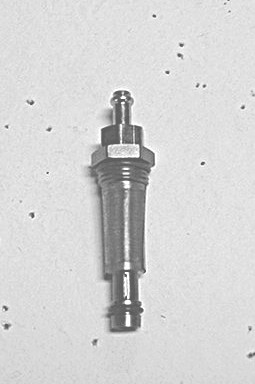
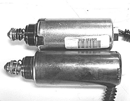
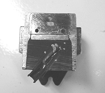
Image #6784
shows the fuel inlet fitting, with mesh filter screen. Image
#6770 illustrates the visual differences in construction, of the 1st and 2nd
design electrical fuel shutoff solenoids. Note that the fuel shutoff solenoid is
the secondary means of shutting off
fuel flow. The PCM is control of primary fuel cutoff, with the fuel control
solenoid.
The lower solenoid typically leaks from the crimped area at the top. There's not
usually any drivability concerns, just symptoms of fuel smell and leakage onto
the ground.
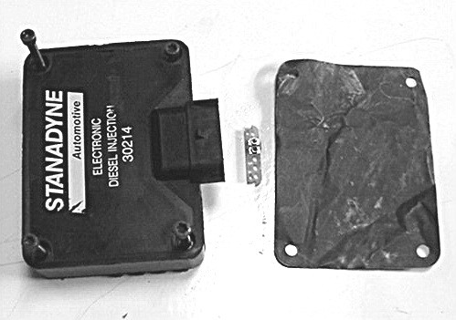
Image #6771
shows the Fuel Solenoid Driver Module with the calibration resistor and heat
transfer pad, which is sandwiched between the module and pump housing. The
resistor is used to calibrate for differences in electrical solenoid winding
resistance, during manufacture and assembly. The resistor must be removed when
replacing the
module and installed to the replacement. The resistors are available from #1 to
#9 and the aftermarket has been experimenting in this area as one way to
increase fuel delivery, in combination with revised boost pressure sensor
calibration.
The module houses circuitry and two transistors, which receive the output
signals from the PCM, for fuel solenoid control. The fuel solenoid is either
open or closed, it is
not pulse width modulated in order for the control valve on which the solenoid
plunger acts, to seat and unseat, for flow control. the module, as is typical of
computer -
controlled systems, provides feedback signals to the PCM, to indicate solenoid
closure signal time.
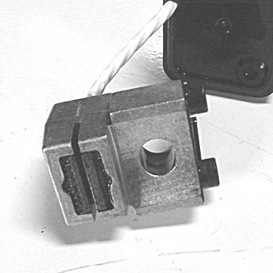
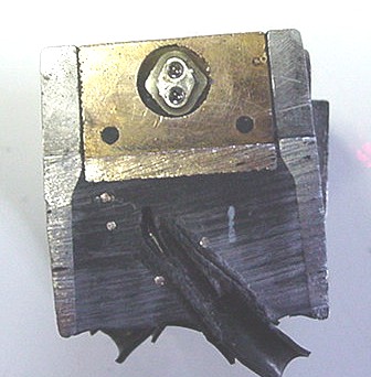
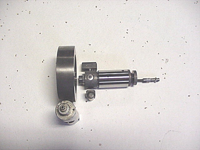
Image #6774
shows the famous optic sensor and the shaft mounted disc or tone wheel as some
call it. The larger area ahead of
the optic sensor, mounted on the shaft, houses the fuel transfer pump. To the
rear, the slotted area houses the four roller and shoe assemblies
which run internally on the cam ring to compress the rotor plungers to increase
fuel pressure for injection. Also, internal to the optic sensor, is a thermistor,
used for
fuel temperature feedback to the PCM. 512 windows, equates to 64 windows for
each single cam reference window.
The disc has 512 windows around its outer perimeter, which are used to generate
the high-resolution signal. Slightly inboard, there are 8 windows, providing the
cam reference pulse signal.
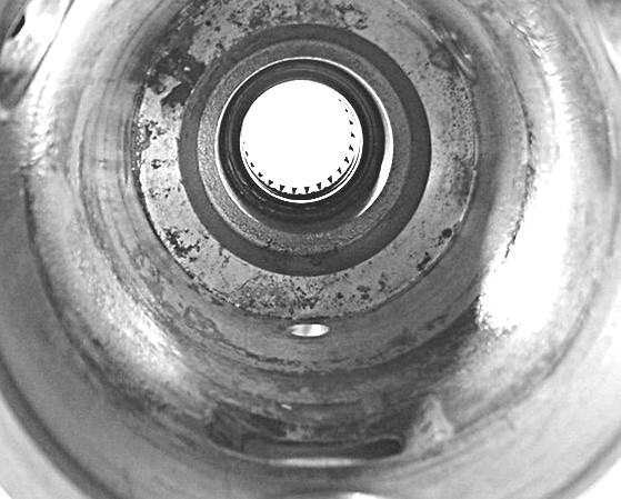
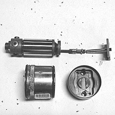
Image #6776
shows the lower end of the sensor, through which the disc rotates.
Image #6779
illustrates the light emitting half of the cutaway section of the optic sensor.
Each time a window or slot in the disc aligns with the light from the sensor, it
passes through to the their half Image
#6780. The continual on and off pulsing, as the light is blocked and allowed
to pass, generates the high resolution and cam reference pulses to the PCM.
Image #6778
shows severe pitting, water/contaminant corrosion damage to the internal
surfaces of the pump housing.
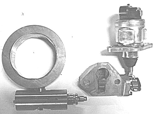
Image #6781
illustrates the relationship between the cam ring, advance piston and timing
stepper motor. The small casting is used to house the linkage, which converts
vertical motion of the stepper motor, to horizontal motion. A lever inside the
casting, bears on the end of the advance piston, against internal hydraulic
pressure. The cam ring rotates to advance or retard timing, as determined by
pressure and the PCM. (Oops- Cam ring is flipped over from actual installed
position inside the pump housing).
Image #6782
shows the cam ring, rotor with plungers and the roller and shoes, which bear on
the plungers to provide injection pressure. The rotor is engaged to the main
shaft, with a slotted drive tang. As the rotor rotates, the inlet ports allow
fuel flow internally, through the spring loaded fuel control valve, into the
"Fill/Spill" chamber.
The upper shoe and roller are placed as they would be installed, while the shoe
and roller underneath the rotor have been rotated 180 degrees to illustrate
their cross section.
Image #6783
shows the rotor, control valve and the main fuel solenoid components. The
solenoid plunger, when drawn through the magnetic field of the solenoid, acts
directly on the spring loaded fuel control valve. The solenoid is either in the
on or off position, eating or unseating the control valve in the end port of the
rotor. This allows or prevents fuel flow into the "Fill/Spill"
chamber.
Fuel flow to the individual cylinder fuel lines, is via the rotor discharge
ports into the rear head outlet ports.
Throughout it's life, this injection pump has seen many upgrades, to optic
sensors, fuel shutoff solenoids, driver modules, transfer pump, pumping elements
and others
components. Injection pump longevity and reliability, is extremely dependent on
the pump receiving a constant supply of clean diesel fuel under pressure. Failed
lift pump or
related components, serve to increase the internal pump operating temperatures,
causing fatigue and subsequent failure of the pump internal electronics.
Kits are available in the aftermarket, to reduce internal pump operational
temperature, by relocating the driver module from the pump housing, to a finned
mounted plate in the cooler airstreams. Module life can be significantly
increased, by reducing the operating temperature of it's two internal
transistors, with more effective heat transfer to this cooler mounting location,
which is able to dissipate heat more rapidly.
In addition to the optic sensor signal, the system uses a number of familiar
5-volt referenced signals, to the PCM for fuel control, as in most automotive
and light truck. I
hope that these images are able provide some insight to the internal workings of
the DS4831 EFI injection pump.
Sincerely.
Martin Smith
Technician/Educator/Instructor
Reprinted
with permission.
