|
|
|
|
Motor Swap 101, Part IThis page if the first of a series detailing motor swapping basics. Much of what is explained here will apply not only to a V8 Z, but to any hybrid vehicle. Pick Your ComboThe first thing to do of course, is to find the ideal body. In my case I wanted the performance of an early 70's late 60's exotic but without the price tag. This meant the car had to be light, nimble, efficient, reliable (o.k., so most early sports cars were not reliable), and have more power than necessary. Next, pick a motor tranny combo. I chose the 350 Chevy and an auto over-drive. This is a very good combo for a daily driver. If I intended on autocross, the choice would be 350 Chevy and 4 or 5-speed. If I planned on drag racing, my choice would be a 406 and a TH350 or Powerglide.
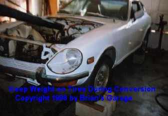
Before DisassemblyBefore you remove the original driveline, certain measurements should be taken. Measure the trim height (a reference for later custom springs). This is measured from the ground, through the axle centerline and to the fender lip. Measure at all four corners and record. Next, locate the crankshaft centerline (a reference for installing the V8, helps to keep your driveline in phase) relative to points on the crossmember or other portions of the body that will not be modified. Label all the wiring using masking tape and PERMANENT marker. Label where and what all the wire under the hood did. This includes the lighting harness. DisassemblyNow it is time for disassembly. Mark three points on each hinge and the same points on the hood. Remove the hood. Remove the driveshaft and tranny crossmember. Disconnect all the wiring, cables, and linkage. Pull the motor and tranny as a unit. With the motor and tranny sitting on the garage floor, do your best to measure the distance between the motor mount center and the crossmember mount center. Take this and compare to your new motor and tranny dimension. This will give you a good idea of what kind of mods must be done to the crossmember mounting location and driveshaft length.
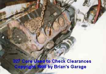
Checking Clearances Now it is time to check clearances.
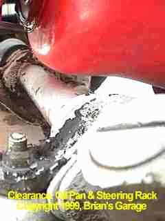
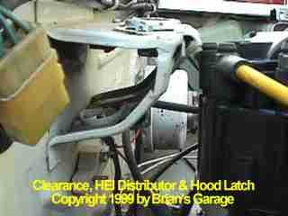
Next, while maintaining centerline, move the engine as far back to the firewall as possible. This will optimize your vehicle center of gravity. Wooden blocks may be used to temporarily position the unit. Observe possible interference points between firewall and distributor also tunnel and transmission. In my case, the hood latch bracket occupied the same area the distributor normally would. I moved the engine far enough forward that I could get the distributor in and out (later I moved the engine further back to allow clearance up front). A rule of thumb is, "a minimum of 1/2" clearance between all engine components and the chassis" (includes distributor, air cleaner, oil pan, etc). This will accommodate any shifting and deflection in the system. Next, approximate the final angle of the tranny tailshaft by leveling the carb pad. Use a torpedo level and level both front to rear and side to side. This will show any interference between the transmission and tunnel. In my case, I had to remove the factory transmission mounting points. The hood, (bonnet for you Haynes readers), should be remounted and aligned with the marks made previously. Loosely stack on the intended intake manifold, carb and air cleaner. Slowly lower the hood and check for interference. If any is detected, the centerline must be dropped.
Now, loosely bolt on a water pump. If you plan on using a mechanical fan, bolt it on too. You will probably be using a custom radiator. There should be about 1/2" between the fan blade and radiator; or if running electric fan, 1/2" between water pump pulley and nearest point of fan. On a Z car, the radiator must be small. It must fit between the frame rails, lower than the hood, but also not hang below the core support too far (curb munchies). A standard brass/ copper radiator is not efficient enough given the space limitations. I recommend an Aluminum. A two core aluminum will cool as well as a four core copper/ brass. For more information check out "Griffin Radiator Install".
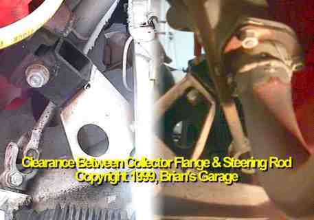
Some swaps may require tweeking of the header. Usually this entails heating and bending and possibly dimpling with a ball peen hammer. I didn't have this problem with my swap. Let's move on to part two..... |
|
Questions or Comments? E-mail me at: [email protected] . Copyright �1996, Brian's Garage. Property of Brian Holdeman, P.E. This page was last edited on 12/28/01. This page hosted by |