by Rich Hirsch
Alfas sold in the US from '69 to '81 used Spica fuel injection. An important component of the Spica system is the theromostatic actuator. The thermostatic actuator (TA) is Alfa's version of a choke and a fast idle cam. The plunger in the TA pushes on an adjustable screw in the Spica pump. When the engine is at operating temperature, the actuator plunger should fully extend and move the lever at the back of the injection pump to 0.0 to 0.019 inch from the reference screw. The farther the control arm is from the reference screw at any given temperature, the richer the mixture.
Over the years, the TA leaks fluid and the plunger doesn't extend as far as it should. This results in the car running richer than it should. Ordinarily at this point, you'd buy a rebuilt TA or replace the TA with the Alfa Ricambi "Sure Start" mechanical actuator. I've found a third solutionrepairing an out-of-spec thermostatic actuator by opening the connecting tube, refilling with hydraulic fluid, and then resealing the tube using a compression fitting. I did this two months ago and the repair seems to work without problems. This article describes the procedure.
A new rebuilt TA is ca. $200US if an old TA is sent in with the order (core value is ca. $100US). This repair involves breaking the connecting tube of the TA which, according to one source does not make the unit useless for core value. (You may want to check with your potential TA supplier to see if this is the case with them.) Then, if you decide to bail out of this repair procedure, you can still get a rebuilt unit and get cash for an old TA.
$200 seems like a lot of money for a rebuilt TA, but according to a recent Alfa Ricambi ad, their rebuilt TAs use new actuating rods, bushings, return springs, seals, and stainless steel connecting tubes. Also, they're guaranteed for 2 years.
The TA I selected to repair was in good condition (i.e., the piston was not coroded and the connecting tube was intact), except for piston extension. Instead of being 23 mm (mounting flange to piston tip length), it was ca. 17 mm. Here is the procedure:
Tools:
set of needle files                       3/32" drill bit
1/8" stainless steel (or copper) tubing   brake fluid
small vise grips with padded jaw          heat gun (or hot water)
accurate thermometer (70 F to 180 F)      1/8' compression fitting
brazing rod for SS tubing (or solder for copper tubing)
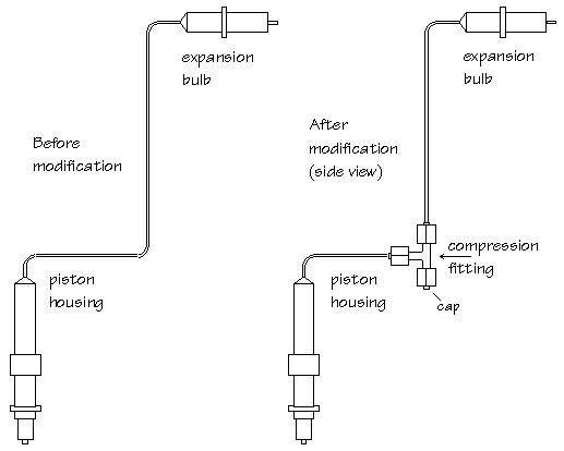
1) Cut the 2 mm tube connecting the expansion bulb to the piston housing using a small flat file at the tube's intermediate mounting bracket. Remove the intermediate mounting bracket and set it aside.
2) Use a file to remove any corrosion from the ends of the tube back from the break 5/16". Make sure the steel is nice and shiny so a good braze or solder joint can be made.
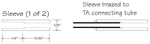
3) Use 1/8" stainless steel (SS) (or copper) tubing to make two adapter sleeves that will slip over the steel connecting tube ends. This is necessary since a 1/8" compression fitting will be used to rejoin the connecting tube. In terms of tubing material, SS tubing is preferred over copper because it's stronger and therefore, the repair will last longer. The disadvantages of using SS tubing are that it must be brazed rather than soldered, it is more expensive, and harder to find.
4) Cut a 3" or 4" piece of 1/8" tubing. Secure the tubing in a vise at the center of the tubing (the two ends are used to make sleeves). So a good seal can be made, sleeves must be free from nicks and scratches.
Use a round needle file to enlarge the diameter of the tubing. Then test fit the sleeve over the TA tube. You are done when the sleeve fits snugly over the end of the connecting tube to a depth of about 1/4". You can decrease the diameter of the TA connecting tube with a small flat file, if this is easier.
When the sleeve is done, cut the copper tubing to a length of 9/16" using a Dremel tool with a small cutoff wheel or a small file. Use a file to dress the end of the sleeve so it's square:
If using copper, make sure the copper sleeves aren't too thin. In some cases the copper may be paper-thin if the filing was not centered. It's important to do the sleeves well. (This is probably the most difficult part of the whole procedure.)
5) Remove with a syringe, shake, or wick out about 1" of hydraulic fluid from the TA tube ends. Do this to prevent heat from the soldering iron from carbonizing the fluid. Slip a sleeve on a connecting tube end and braze is using SS sleeves, or solder if using copper sleeves. (If soldering a 60 Watt iron and electrical grade rosin-core solder work well. I think a torch probably puts out too much heat.) Repeat for the other tube end.
It's very important that the braze/solder joint be well done. Use enough material and make sure there aren't any pinholes.
6) Fit and tighten the compression fitting (don't worry about replacing the fluid yet).
7) Open the compression fitting and fill the tube ends with brake fluid. Use a syringe to fill the tubes or just dribble the fluid in and use a thin piece of wire to work out all the air bubbles.
8) Clamp the heavy metal ring on the piston housing in a vise (gentlely but firmly) with the piston pointing up and connecting tube pointing down. Make sure the connecting tube has a drop of hydraulic fluid on it and retighten the fitting.
9) Heat the expansion bulb with a heat gun or hot water until the piston extension is 25 mm as measured from the bottom of the mounting flange. At this point, grab the piston gentlely but firmly with a small pair of vise grips with padded jaws (for padding I used a strip of rubber from an inner tube). This prevents the piston from retracting when the compression fitting is opened. Be careful, the piston is fairly easy to scratch!
Don't apply excessive heat to the expansion bulb! Getting a piston extension of 25 mm may require two stages. That is, heat the bulb, clamp the piston, open the fitting, cool the bulb, fill with hydraulic fluid, tighten the fitting, repeat.
10) Open the compression fitting at the top nut and immerse the expansion blub in cold water. Make sure the tube ends remain filled with brake fluid. Let the TA bulb sit for about 15 minutes at 68 F (20 C), then reassemble and tighten the fitting making sure no air is included. Release the vise grips and test the piston extension. It should be 23 + or - 1 mm (for '76-'79 cars). If it's off, repeat step 9 above, compensating for the amount it's off.
11) Next, test the high temperature piston extension. At 175 F (79 C) it should be 29 + or - 1 mm (for '76-'79 cars). Check for leakage at the fitting and solder joints.
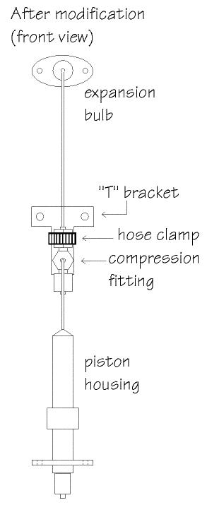
12) In mounting the TA, be sure to secure the compression fitting to the intermediate TA clamp. One potential problem with this repair procedure is that we've introduced a fair amount of mass (the compression fitting) where previously there was very little (just the mass of the TA connecting tube). If the fitting is allowed to vibrate freely, a solder joint could fail or the connecting tube break from the constant flexing. Tie the fitting down!
I constructed a simple "T" bracket that mounts just like the original TA intermediate mounting bracket. The compression fitting is then lashed to the "T" bracket using a small hose clamp.
13) After installation, occasionally feel the fitting and surrounding tubing for the presence of hydraulic fluid. If you find any, there's a leak that needs fixing. As an indication of plunger extension, disconnect the long rod from the bellcrank after the engine has reached operating temperature. The pump gap should be 0.0 to 0.019 inch. If it is significantly greater, there's a leak.
Note on using stainless steel sleeves:
14) The reliablity of the repaired TA is improved if stainless steel (SS) sleeves
are used instead of copper, and the SS sleeves are brazed to the existing TA tubing,
rather than soldered. To use SS sleeves, modify the above procedure as follows:
A) Rather than drilling out the sleeve as indicated in step 4), use a round needle file
to enlarge the diameter of the SS sleeve to accomodate the TA tubing. Also, it helps
to file down the TA tubing.
B) Rather than soldering the SS sleeve to the TA tubing, braze it. This results in a
much stronger bond.
C) One other modification I made to the procedure is to use a 3-way "T" coupling,
rather than the 2-way coupling shown in the illustrations. The advantage of this is
that the TA more readily conforms to its physical configuration and to add more
hydraulic fluid, you simply grab the piston as in ??? and open the cap. Then
immerse the bulb in cold water as the fluid level falls, simply add more fluid.
Since the SS tubing
has a thinner wall thickness, there is less material to remove and the resulting
Since the SS tubing has a thinner wall thickness