FF chassis number 123, London. July 1998.
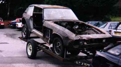
Few FF transmissions were dismantled in the past, but now as the rubber seals reach the end of their life, replacement necessitates removal and inspection... This is what you can expect to find. This particular transmission spent most of its life in the Everglades, fitted to a car that, when finally removed from the swamp, was up to its axles in mud...
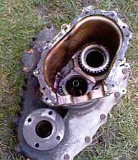
As can be seen from the following photos, the FF transmission is massive. The fact that Jensen managed to conceal this sculptured alloy masterpiece inside a car, and install a differential ahead of the engine while only increasing the car in length by 4 inches, is a testimony to the ingenuity of the engineers.
Removing the engine and transmission was fairly straight forward, as the front engine frame, radiator and bonnet had already been removed. This is how we did it.
These photos were taken over 6 months since I last saw the actual transmission, so the explanation is more than likely wrong in one area or another. however, here are things as I recall them...
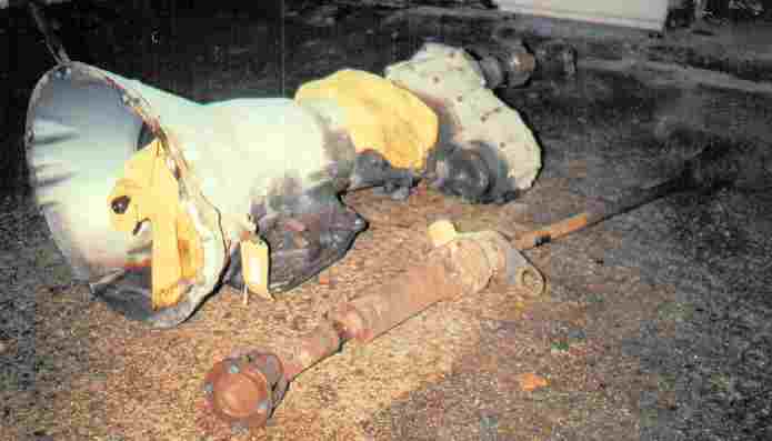
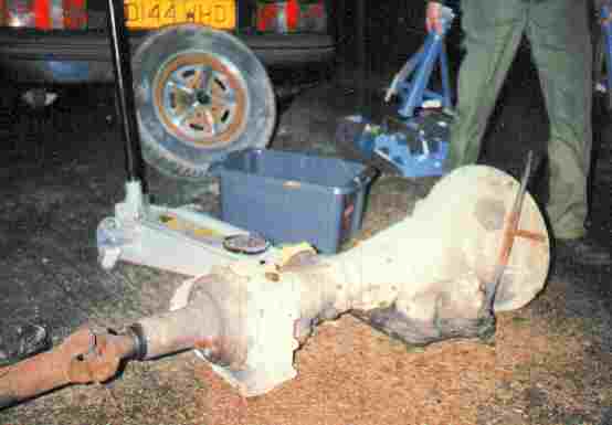
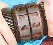
Once out of the car and dismantled, the tail housing and then the centre diff casing were removed...
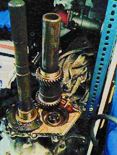
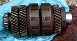
The large shaft on the left is the main output shaft from the
torqueflite automatic transmission. The shaft on the right is a slave shaft
driven off the main rear output shaft... Ultimately, the front prop
shaft is driven off this slave shaft, via a set of triplex (on early cars)
or
duplex chains on later cars. The two gears on the slave shaft to the
right of the above picture, mesh with the top and bottom gears on the
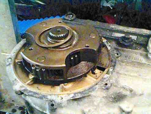
two way clutch assembly, seen at the very bottom of the page. The
two way clutch sits above that castled gear on the face of the casing on
the above photo. Power from the transmission output shaft (above
left) is transferred via the splines at the top of the shaft to a
planetary gear differential. A large tubular shaft (not shown!) slides
over the shaft on the left, running on the bearing at the bottom of the
output shaft.
This tubular shaft has gears at the top and bottom of the shaft. The
bottom gear drives the two way clutch, while the top gear drives the planetary
gears in the centre diff. When the transmission is locked up or being driven
along a straight, this large tubular shaft and the transmission output
shaft rotate at the same speed and in the same direction, minimising wear
and friction. When one of the prop shafts moves at a different speed
due to loss of traction, this causes the tubular shaft to rotate
at a different speed to the transmission output shaft,
winding up the two way clutch one way or the other. Once the clutch
engages, it forces the transmission output shaft and the large tubular
shaft to turn at the same speed, totally locking the centre diff... The
diff is now completely locked, and no power loss through viscous couplings
is experienced at WOT. More to the point, with no viscous coupling, no
drag is experienced when cruising, making the mechanical clutch transmission
the most fuel efficient locking mechanism to date. When going into a corner
at speed just prior to entering a 4 wheel drift, an instant and reassuring
positive feel comes through the steering as the diff locks, and the vehicle
can be driven and steered using both throttle and steering wheel. A car
equipped with a viscous diff feels slightly slower to lock up, and can
unlock too early in the corner, unless a wide throttle opening is maintained.
The mechanical clutch unwinds imperceptibly, and is devoid of the front
rear torque shift than can sometimes be felt with a viscous clutch as it
unwinds too early. No wonder a racing car equipped with an FF AWD transmission
was Sterling Moss' favorite car of all time!!!
Below is an end view of one end of the gears on the 2 way clutch assembly.
This is the reverse gear sprag assembly, which disables the clutch
while the car is in reverse. Presumably this means there is no ABS
or AWD when traveling in reverse!
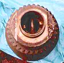
The photo below shows the planetary gears. The Sun wheel is not shown, but it fits over the outside, with teeth cut on its inner surface. Imagine a large tea cup with teeth cut on the inside top of the rim. The drive shaft yoke then attaches to the base of the cup, as the cup sits upside down over the planetary gears.
So how does this wonderful clutch lock up??? It looks like two motorcycle
clutches back to back. That is basically all it is!!! Simple and effective!
The clutches engage by turning a gear at one end of the assembly in the
opposite direction to the other. Ball bearings in groves cut into the shaft
move the two clutches together when the gears are moved in opposite directions...
This photo shows the clutch unlocked:
The photo below shows the clutch fully locked. Special tools exist for servicing this part.
Under heavy braking, when one axle looses traction, the clutch will quickly lock. A partially free wheeling weighted but small flywheel driven off the clutch mechanism, detects this sudden change of speed as one of the gears on the end of the clutch is accelerated as the clutch spins freely, then decelerated as the clutch locks... The deceleration caused by the lock up is detected as the small flywheel overruns, activating an electrical switch, which triggers a relay (The maxaret valve) dumping vacuum from the servo, creating the familiar ABS judder as the car is brought to a halt. However, in its day, the juddering was regarded by many as a major fault of the vehicle, even though all ABS braked cars since have behave like this (at least at the time of writing!). ABS was a new and unnerving experience for road testers 30 years ago. The only response the factory could possibly provide was to disconnect the ABS. This contributed to controversy and bad press.
The system is not totally fool proof, but under normal spirited driving
should perform well. In extreme situations, like approaching a hump back
bridge at full or heavy throttle, the acceleration of the wheels as the
car looses traction at the top of the hump (possibly with a wheel becoming
air borne) could cause the ABS (Maxaret) dump valve to trigger on acceleration.
This is not a problem, as the brakes have not been applied yet.
However, as soon as they are (for a sharp left after the bridge, for
example), the ABS mechanism is in mid trigger. As this was caused by loss
of traction during acceleration, it is a flaw of the ABS to trigger. So
the instant when the brakes are applied, the ABS is finishing a pump cycle
caused by the acceleration. The driver feels that the brakes have momentarily
failed, applies more foot pedal pressure, making things worse...
I read of this hump back bridge report in the J.O.C. mag, and the explanation above is my theory based on a brief visual examination of the system. I am not a professional mechanical engineer, and all text and descriptions should not be taken as fact.
I have never experienced the FF ABS "in anger" myself. To this day, some people I talk to like it, some people don't...
However, I have experienced the duo-lock effect. This is when the diff locks up under braking, forcing a locked wheel to turn at the speed of the other three... Testing the car after a braking overhaul, the car would pull to one side as one caliper was not working at full power. Applying the brakes excessively in a wide open space, so as to lock 3 of the wheels, the car would veer to one side momentarily with some tyre screech, then brake in a straight line.