The KAP-II Project
One day while surfing the Web doing research on something or another, I came across a link for Kite Arial Photography (KAP). I Thought to myself "Hey, that's cool, I should do that!" I decided to make it my Winter Project, giving myself until Spring to have it completed.
Of course Winter came and went and I only had a little bit done. Then Spring came and went and I had scarcely any more done. Then finally when Field Day was just a few weeks away in early Summer, I knuckled down and really started working on it. I had everything working breadboarded on the workbench, that part was easy; believe it or not, the hardest and most time consuming part of this project was packaging everything up in a "crashbox" so it wouldn't be damaged if it fell from the Kite.
Table of Contents:
KAP-I:
KAP-I was my first attempt, it was a Proof of Concept model. Since it could be destroyed by a fall from the Kite, I made everything as cheaply as possible. I used a Picaxe 04M, hacked a cheap digital Camera I had picked up at a Yard Sale for $2, and crammed everything in to a small box packed with bubble wrap. KAP-I ended up Weighing 325 Grams (11.46oz.) It worked, but the first kite I built was too small to lift it (in anything less than storm force winds.)
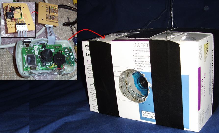
Top/Left: Front of Controller Circuit.
Left: Controller Circuit Connected to Cheap Digital Camera (I soldered directly to the camera's circuitry.)
Right: KAP-I Crash Box (Camera crammed in and stuffed with Bubble-Wrap to protect everything.)
Total Weight: 325 Grams (11.46oz.)
Link to KAP-I Controller Code.
I tried flying it, but it spent most of it's time either on the ground, or just a few feet above it; the wind just wasn't strong enough to lift it (actually, it was a good wind - the kite was too small.) However, I did get one good picture I got out of KAP-I
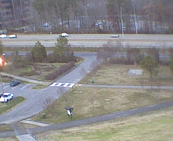
With a sudden gust of unusually strong wind, the Kite lifted the KAP-I rig way up in to the air and I got one good picture out of it.
(I paid $2 for the camera, but judging by how blurry that picture is I'm not sure it was worth that much.)
Since KAP-I was, basically, a success (it achieved it's primary Proof of Concept goal) I moved on the KAP-II.
Top
Schematics:
Schematic - Block Diagram:

Block Diagram Description: The outputs from Air Pressure, Temperature, Wind Speed, and Battery Voltage Sensors are feed in to the inputs of a PicAxe 18X. It Processes the raw sensor inputs, and then triggers the Camera (using a Servo) and Transmits the Raw Data. A Receiver captures the Data, converting it to a RS-232 Data Stream. The Data Stream is feed in to a Laptop that Archives the Raw Data, Filters and Decodes the Data, Archives the Decoded Data, and Displays the Decoded Data on the Screen.
Schematic - KAP-II Avionics:
| KAP-II Avionics |
Description |
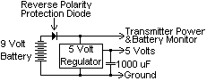 |
Power is supplied by a 9 Volt Battery, through a Reverse Polarity Protection Diode, to the Transmitter and the Battery Monitor, and then through a 5 Volt regulator to the rest of the circuitry. |
 |
Programming Interface to Computer. |
 |
Reset Circuit is a Momentary Push Button. |
 |
The Air Pressure Sensor is a MPXA4115A Absolute Pressure Gauge. |
 |
The Temperature Sensor is a Dallas DS18B20. |
 |
The Wind Speed Sensor consists of a Phototransistor interrupted by a PC Fan, with adjustable sensitivity. |
 |
Setting a Jumper puts KAP-II in Wind Speed Calibrate Mode, allowing you to adjust the sensitivity and see the results on the LED. |
 |
The Battery Monitor divides the Voltage down by (approximately) 1/4 and then measures it with an ADC input. |
 |
The Camera is Triggered by a mechanical linkage with a Servo. |
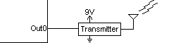 |
The Raw Data is sent out the Transmitter. |
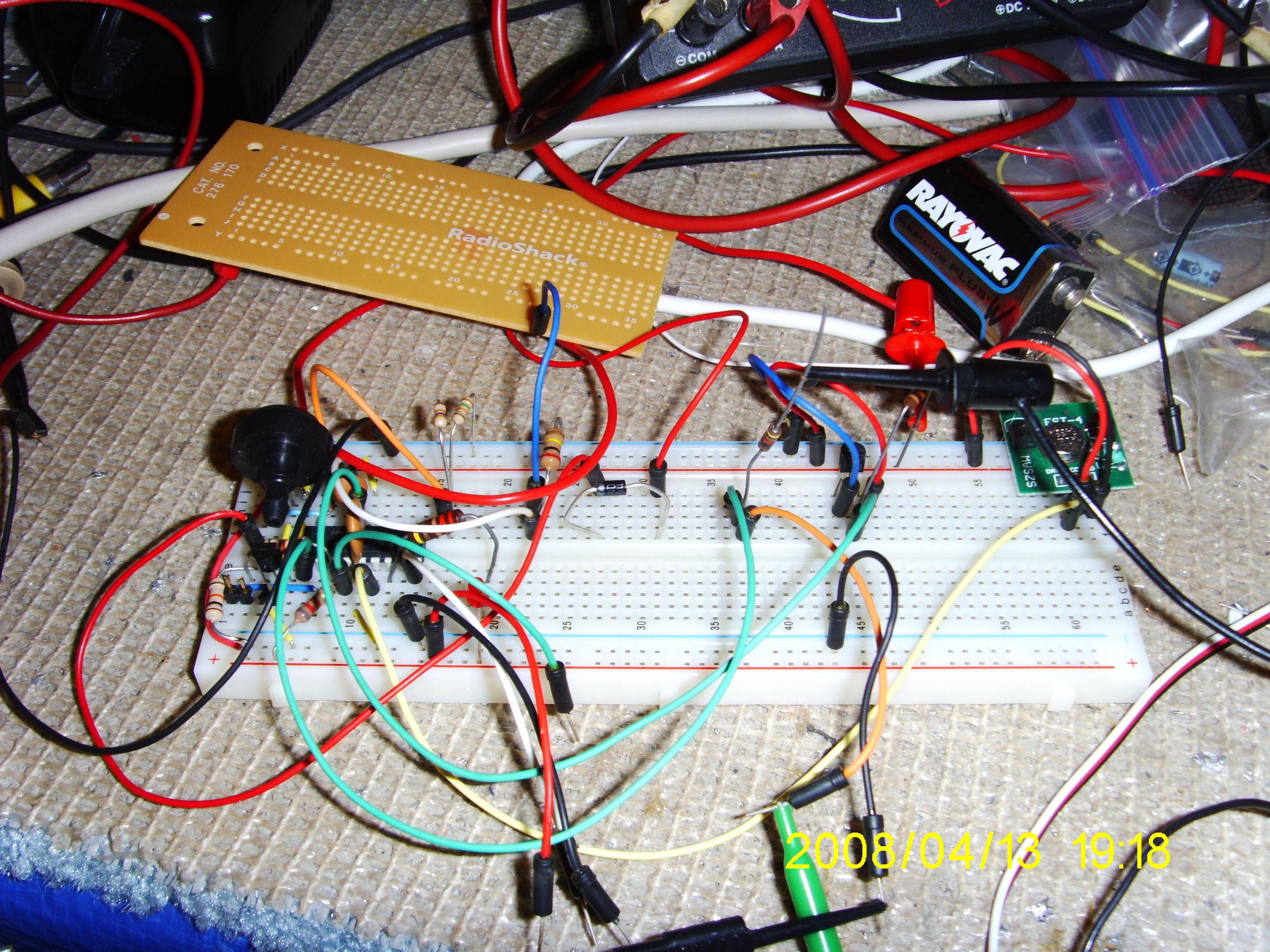
KAP-II breadboarded: That black thing on the left is the Air Pressure Sensor; the 433MHz Transmitter is that green thing on the far right.
Link to KAP-II Controller Code.
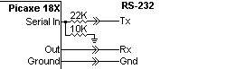
Schematic - KAP-II Receiver:
| KAP-II Ground Support Receiver |
Description |
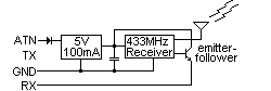 |
The KAP-II 433MHz Receiver is powered by the ATN Line of the Serial Port. The diode is necessary because when you turn the Radio Off, the ATN line goes to minus 15V. The Transistor was necessary because the output of the Receiver couldn't drive the RX line directly. |
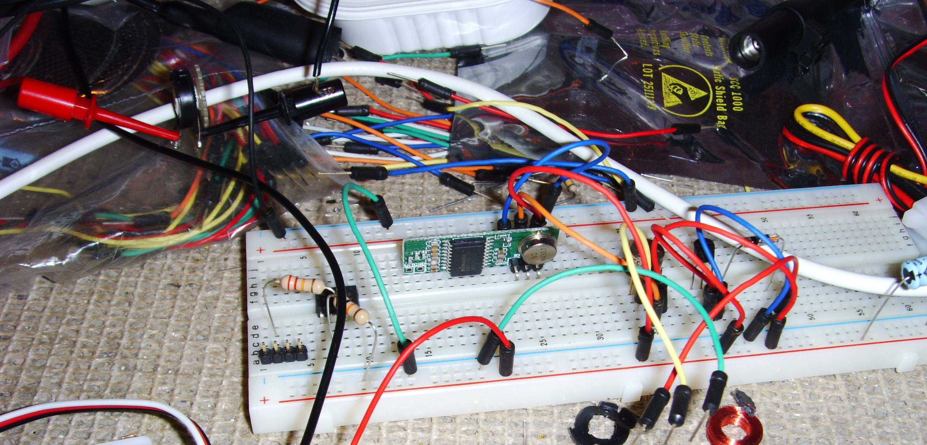
KAP-II Receiver breadboarded: The KAP-II 433MHz Receiver is powered by the ATN Line of the Serial Port.
Some day I will probably get around to soldering the Receiver on a circuitboard, but for now I'll just use it on the breadboard.
Top
Wind Speed Sensor:
Anemometers are damned expensive (check E-Bay and see for yourself) and there was no way I was going to pay that much for one; so I decided to build my own. The heart of the Wind Speed Sensor is a PC Fan with the guts taken out, a Phototransistor epoxied inside, and slots cut in the Fan housing covering the Phototransistor to act like an interrupter. It was going to sense the ambient light, and had adjustable sensitivity so it could be tuned to the light level that it would be used at.
At least, that was the original idea. However, when I went to calibrate it by hanging it out the window of my car I found that it was too sensitive to variations in light as it dipped in and out of the shade; I got readings all over the place. What I really needed to do is to completely enclose it, and use an internal lightsource. I may use an Interrupter from an old discarded mouse. But, since Field Day is only a week away, I'll just split the difference from my Calibration runs and use a compromised value; for now it's really only able to tell you if the wind is blowing or not.
The rest of the sensor consists of a Phone Cord Untangler providing a swivel and electrical connection, and a tail to steer it into the wind.
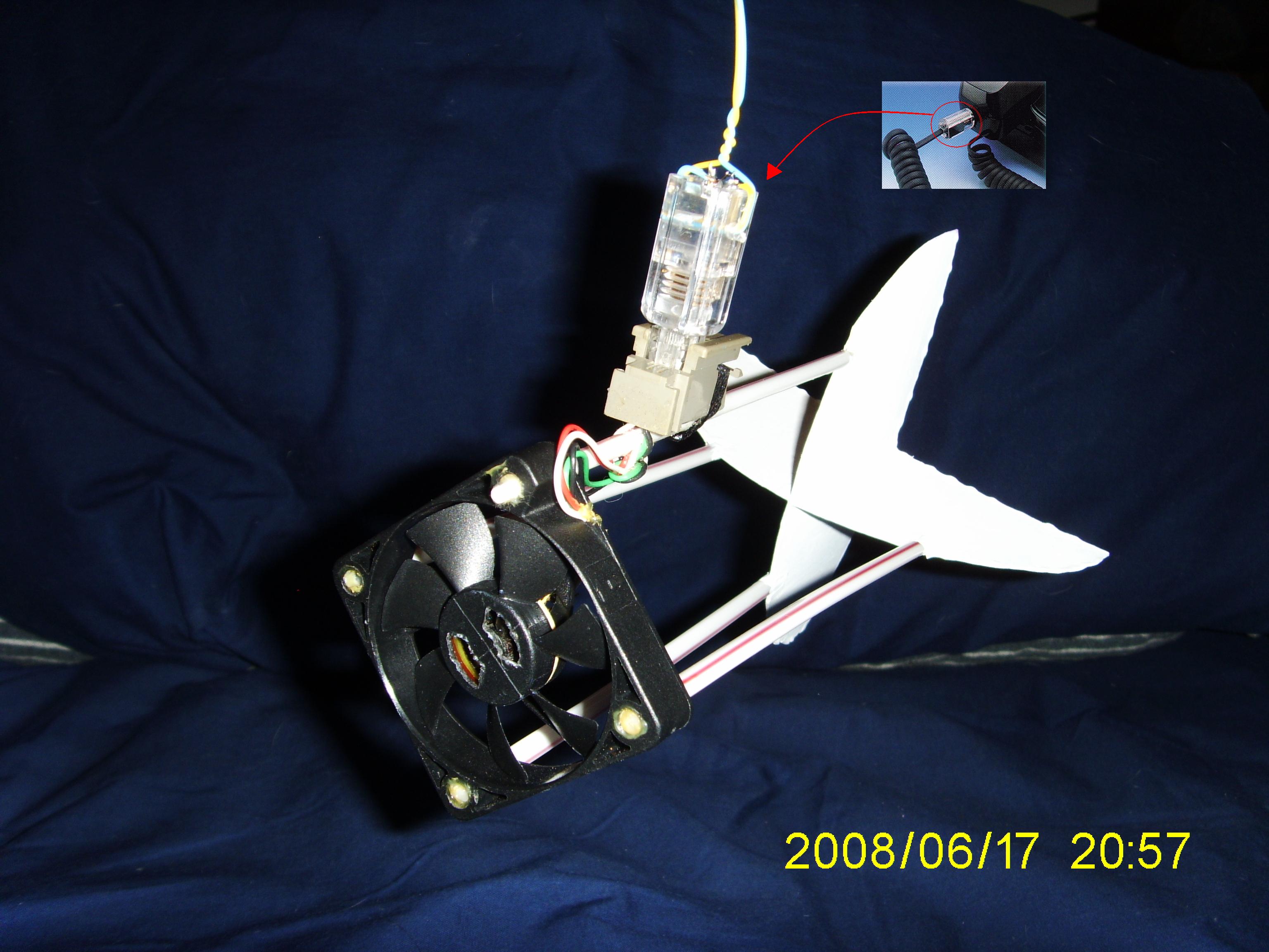
Completed Wind Speed Sensor; the swivel is a Phone Cord Untangler allowing it to steer into the wind.
Top
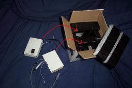
Crash Box:
Since the camera was fairly expensive (about $100 on E-Bay including shipping) plus about $40 in other electronics that have the potential to be destroyed if it fell 100 feet or more from the Kite, I decided to build a Crash Box to house the camera and all the electronics. It is a small shipping box with lots of bubble-wrap to protect the contents. Holes are cut to allow the Camera to see out, and the Temperature Sensor, Wind Sensor, and Antenna to stick out the bottom. The whole idea is to make a catastrophic fall survivable. Think of it as a Crash Helmet for electronics.
Top
Final Assembly:
Steps for Final Assembly and Launch
| Step |
Description |
Picture |
| 1) |
The Camera is turned on and put in a cardboard insert with a Servo held in place over the Shutter Button, and holes so the Camera can see out. |
 |
| 2) |
The Motherboard is turned on and put in another cardboard insert with holes for Servo Connector, Temperature Sensor, Wind Speed Sensor, and the Antenna. |
 |
| 3) |
The two inserts go in the Crash Box cut-outs - aligning the Camera Lens with the hole in the front of the Crash Box; wires for the Temperature Sensor, Wind Speed Sensor, and the Antenna stick out the bottom of the Crash Box. |
 |
| 4) |
The top padding is put in the Crash Box and it is closed up. |
 |
| 5) |
The Wind Speed Sensor is snapped on to its connector.
(This is a good time to reset the Initial Altitude Reference on the Ground Support Software, and make sure everything is working. You can easily test the Wind Speed Sensor by blowing on it.) |
|
| 6) |
The Crash Box is hung from the Kite/Balloon or other source of Lift. |
|
| 7) |
One final check on the Laptop that it is receiving a signal from the KAP-II rig, and you can launch it. |
|
Top
Ground Support:
Ground Support is the other half of the equation; it consists of a 433MHz receiver, a Laptop, and receiving side Software. The 433MHz receiver reconstructs the RS-232 signal sent by the Picaxe-18X and feeds it in to the Serial Port of the Laptop. The receiving Software...
- Reads the Raw Data Stream.
- Archives the Raw Data Stream.
- Filters unwanted characters.
- Decodes the Data Stream.
- Archives the Decoded Data.
- Displays the Decoded Data to the user in various units of measure.
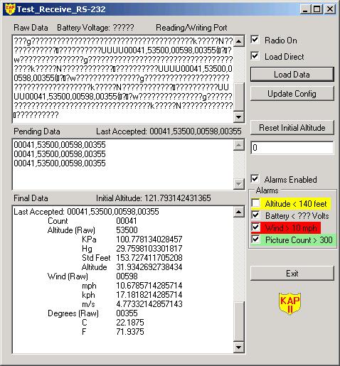
On the left from the top down are Textboxes for...
- Raw Data.
- Filtered Data.
- Decoded Data displaying...
- Number of Pictures Taken (Count)
- Altitude
- Wind Speed
- Temperature
On the right from the top down are Controls for...
- Turning the Radio On/Off (it is powered by the Serial Port ATN Line, and this toggles the Line.)
- Load Direct is used for replaying archived Data Streams (it can Load the data directly - very fast, or transmit it out the Serial Port to be re-read - very slow, but useful for testing/debugging.)
- Load Data brings up a File Open prompt where you can select which archived data stream to load (it can read both types of archived data - raw and filtered/decoded.)
- Update Config allows you to update configuration settings in an XML file and change them without having to stop and restart the program.
- Reset the Initial Altitude to a given value (this is subtracted from the current reading to measure the altitude from the ground in feet.)
- Enable/Disable all the following Alarms with one control (if an alarm is activated and enabled the laptop will beep incessantly - hence the reason to disable the alarms.) All the following alarms can also be enabled/disabled individually and have a...
Gray background when there is no data yet.
Green background when inactive (status okay).
Yellow background when activated and disabled.
Red background if activated and enabled (also beeps.)
- Altitude Alarm: Disabled by default, but once the Kite/Balloon is at maximum height you can enable it and will warn you if you start loosing altitude. (Set Point is read from the Configuration File and can be changed on the fly.)
- Battery Alarm: Warns you when the Battery is getting low.
- Wind Speed Alarm: You should never fly a Kite/Balloon on winds that are too high, and this will warn you if the wind speed creeps up after launch (Set Point is read from the Configuration File and can be changed on the fly.)
- Picture Count: Warns you when the number of pictures starts to approach the maximum that the camera can hold. (Set Point is read from the Configuration File and can be changed on the fly.)
- Exit will flush and close any open data archive files, release the Serial Port, and then (of course) terminate the program.
Top
Field Day 2008:
I belong to the local Amateur Radio Club (www.RASONVA.com) and every year they participate in Field Day, which is an international event to practice setting up for emergency communications (and an excuse to throw a party and eat a bunch of unhealthy food.) One day somebody in the club had the idea of putting up a vertical antenna held aloft by a Weather Balloon. Due to my (very limited) experience with my Almost There I project, I was put in charge of that. We did it once, so now it is a deeply entrenched tradition to do it every year.
KAP-II was originally intended to be lifted by a large Kite, but I realized that it could also be lifted by the Weather Balloon on Field Day. I had it working on a breadboard, I just had to solder it, and then package everything up in the Crashbox so it was protected; I thought that would only take a few hours to package it, but it was far more time consuming to do it correctly than I anticipated.
I got everything finished enough to be useable, and two days before Field Day I did a complete Dry-Run Dress-Rehearsal and found that the Microcontroller would randomly hang when the Servo to trigger the Camera was connected. I knew it was highly recommended for Servos to have their own Power Supply, separate from the Controller's, but I didn't have any problems on the Bread Board, so I just soldered it up that way. I quickly re-wired the circuit and added a 1 Amp Regulator just for the Servo, and everything tested out fine after that.
Field Day is all about practicing for real world emergencies
A Helium Balloon makes a Good Vertical Antenna in an Emergency...
|
| Oh sure! You can't get food or water, there is no electricity, the roads are impassable, there are dead and injured scattered all about, but it's easy to get a delicate six foot Weather Balloon and 115 Cubic Feet of Helium; and there is plenty of time to fill it up and launch it. No problem! |
|
I made it! KAP-II was all set to go, but the day before Field Day I looked at the weather forcast and saw that it was expected to be too windy to use the balloon. If the cost of renting a Helium tank was trivial, I would have just gone ahead and gotten it anyway, just in case; but, it was $120 to rent it whether you use the Helium or not. I didn't feel right spending $120 of the club's money when I knew we probably wouldn't be able to use it. I checked with the guy coordinating the event for our club, and he agreed, so we canceled the Vertical Antenna (even without the Vertical Antenna, we ended up with five antenna's to use between three transmitters anyway.) Turned out to be a good call, it was definately too windy to use a balloon. Unfortunately, canceling the Vertical Antenna meant that my KAP-II Project was also grounded.
Top
KiteZilla:
After doing some research on kites, I decided to build a "Scott Sled" which is simply a large sheet of material with two spars for support, so it folds up and transports easily. It's simple to build, but not as good as rigid kite if the wind has a lull. The best to use would be a "Winged Box Kite", but that is harder to build, store, transport, and set up (if you're building a Winged Box Kite on that scale, you may as well be building a small airplane frame.)
Safety: A quick word on safety with large Kites. From all that I've read, working with Large Kites is much different than the little Toy Store kites you flew as a kid; there are stories of people have their fingers "de-gloved" by trying to grab a run away kite string with 40 or 50 pounds of pulling force on it (ouch!) The running kite string acts like piano wire, and will easily cut you to the bone. Wear heavy leather gloves at all times, plan ahead, and use good equipment so you should never get in the position of being tempted to grab a run away string.
I bought a large 9 foot by 12 foot professional quality painters tarp (only in America can you buy something advertised in great big large print as 9 x 12 only to get home and find that the small print says it really measures only 8.5 x 11.5; how do they get away with that? In America of all places? And if they can get away with that, why can't I buy a $10 item and pay them $9.50 for it? I mean if it's fair for them to round up to the nearest whole number, why can't I do the same? Fair is fair. Why do we consumers tolerate this?)
STOP THE PRESSES! I was all about to build this monster size kite, but then I came across NASA's KiteModeler program. I entered the dimensions I intended to use and realized that in a 30mph wind, this thing would lift me right off the ground! (It's not unreasonable to design for 30mph; if you plan to use it in 10 to 15 mph winds, it should be able to handle an unexpected 30 mph gust.) So then I entered the dimensions of the first kite I had built and, according to NASA's KiteModeler program, my original kite should have lifted my KAP-I rig in even a mild 6 mph wind. Then I realized that I was just so frustrated at my first attempt that I figured I'd scale it way up, and a painter's tarp was the first thing that came to mind. I'll have to re-test my first kite again. I can't explain why it didn't work (while I didn't have any gauges to measure the wind speed, it did rustle my hair which makes me think it must have been 10 to 12 mph or so.)
Top
KAP-II© Copyright Ken_S. 2008