project
#7: MDEC64
64 points MIDI-to-Parallel decoder
This unit is available thru www.midiboutique.com
Description:
This
project starts new line of projects:
MIDI receiving/decoding units. The main purpose is to drive pipe relays
(valves) in classic pipe organs using MIDI interface. Using this unit
different devices can be built also. For example, Light Music keyboard
instrument can be easily assembled, based on mdec64. In this case,
lamp drivers should be used for connecting lamps to the unit's outputs.
Since the first purpose is driving organ pipes valves, examples for such
drivers are shown below the unit schematic.
Schematic:
(click
on schematic to get picture enlarged)
Used
parts:
U1:PIC16F84.
U2:74LS138
decoder 3:8.
U3..U10:4099
addressable 8-bit latches.
Q1: Quartz
resonator (crystal). Must be exactly 10MHz.
C1,C2:
Capacitors 27pF each. Certain quartz resonators
have these capacitors integrated. If
you use such resonator, there is no need of C1 and C2.
R1: Resistor
2.2k.
R2: Resistor
330 Ohms.
R3: Resistor
220 Ohms.
SW1:
4-bit BIN switch for selecting MIDI channel.
X1: DIN
5 female connector. Used for connecting mdec64 to standard MIDI
line.
D1:
Opto-coupler PC-900 (Sharp) or 6N138 (Hewlett-Packard).
NOTE: The standard MIDI input device must have such opto-isolated
input. This is an standard requirement for every MIDI input. Click here
for more information about interfacing MIDI devices.
The power supply is standard regulated +5v. The pin #14 of U1, and pins
#16 of U2..U10 are connected to Vcc (+5v wire), the pin #5 of U1, and
the pins #8 of U2..U10 are connected to common (ground) wire. These
pins are not shown on schematic.
NOTE: Using external power adaptors with
output voltage more than 5v could damage the unit. As I know there are
no 5v adaptors on the mass market. Making such adaptor is relatively simple
work. You can click here to obtain such
adaptor schematic. It is not required to be an electrician in order to
make such adaptor but a basic knowledge about electrical safety is
a must. I assume that reading this means that you are capable to build
the schematic shown above, thus you are capable to build the adaptor yourself.
The only way to have this controller is ordering pre-programmed chip. Since this is dfm, no HEX file will be published here. The controller is fully customizable, so recognized MIDI messages can vary depending on customer's order. The most standard set of MIDI messages recognized is NoteOn, NoteOff, AllNotesOff, which are enough to control organ pipes. Supported is Running Status. System Common, System Exclusive (SysEx) and System Real messages are also recognized, not being processed in this version. Some of these messages can be processed as well by custom demand.
NOTE: A bit of mdec64 'know-how' is placed on Documents page. This is interrupt routine flowchart diagram and may be interesting for dedicated people. You can see it here (pdf format).
![]()
How MDEC64 looks:
Here is how the mdec64 prototype looks. Instead outputs there are LED's to indicate output status. The picture is taken during 'playing' the great Toccata And Fugue in D-minor by J.S.Bach.
And here
is the production design of the unit (which you can purchase
from me). It has two modifications.
The first one has TTL compatible outputs:

The second one (mdec64b) has output buffers, so it can drive loads at 30V/500mA max.:

Specifications:
- size 5x19cm (approx.2x7.5") standard mdec64
- size 6x19cm (approx.2.4x7.5") bufferized mdec64b
- opto-insulated MIDI-input
- MIDI channel selector
- built-in voltage regulator (input voltage AC/DC 6..12V)
- 64 parallel TTL compatible outputs for mdec64
- 64 parallel bufferized outputs for mdec64b, capable to drive loads at 30V/500mA
- two standard firmware modifications: low notes (note range 1..64) and high notes (note range 65..128), customer defined ranges are also available on request
- NoteOn, NoteOff,
AllNotesOff MIDI messages on selected channel recognized, all
other (including Realtime/SysEx) ignored
Paolo Airasca from Italy developed MIDI decoder based on mdec64 for controlling organ pipe valves (electromagnetic) via MIDI line. Here is how Paolo's PCB looks.
Vern Jones from USA made a version of mdec64 using integrated output drivers (see below).Here is his PCB.
Clicking on the picture, you can download file md64vj.zip containing whole information about Vern's version of mdec64, including:
- modified schematic diagram for using ULN2803 drivers;
- graphical original of PCB;
- components layout.
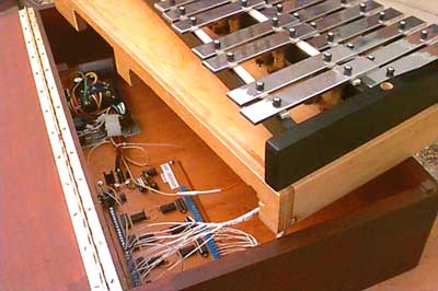
Vern's jewelry project
MIDI Orchestra Bell Box using the MIDI decoder shown above is ready
and working. More information about it can be found on Vern's
site. There are placed also .mid (MIDI) and .rmj
(Real Player, Real Jukebox) files so visitor is able to
hear and compare synthesed and 'live' Bell Box performance. Here
is a picture of Bell Box.
Great work, Vern!
Drivers:
Here
are shown two examples of drivers for switching pipe organ valves or another
types of relays/electromagnets. The maximal current that could be switched
by these drivers is about 2 Amperes. For the most of such devices 0.8
- 1 A is enough.
These drawing are kindly provided/tested by Vern
Jones. Here is a link to Vern's
site.
The left
side of drawing shows how to make valve drivers using power FET transistors
(IRL520), and the right one shows using of power Darlington bipolar transistors(BD677).
NOTE: Both kinds of drivers can be connected
directly to mdec64 outputs. No additional stages are needed.
Another driver solution is using integrated drivers. Vern Jones used ULN2801/2/3/4/5 for his design (shown above). These devices include 8 Darlington transistors with protective diodes on each. They are capable to switch up to 500mA. Here is datasheet (pdf format).
![]()
Details
about how to order pre-programmed chip or ready made unit can be found
here.
The package includes
mdec64 unit and User Manual with fully documented
schematic and MIDI Implementation Table.
Two
models: non-buffered (mdec64)
and buffered (mdec64b)
are currently available. Custom note range is supported, including non-continuous
note ranges.