project
#2: HHS
Home Heating System project
Prehistory:
This
is the heating system wich I built in around 2 months in order to keep
a comfort temperature in my home during cold seasons. Last year I purchased
the main heater. This is an heavy (wood or coal) fuel burning camera with
so called 'water shirt'. Besides, I bought a number of alluminium radiators
and some standard 1/2" water pipes. I had to add a water pump in
order to force a water circulation because there was no possibility to
make denivelation between heater and radiators to achieve natural water
circulation. Then some questions appeared that I had to answer to. The
first question: 'The pump is not designed for uninterruptable work. How
can I make it work for some time interval, then do a pause, then work
again etc.?'. Second question: 'How to keep water themperature between
given boundaries?'.
The answer was: the single chip controller PIC16F84 by Microchip. I had
to build a simple (relatively) 'pump controller' using PIC wich allowed
me to program my water pump work/pause intervals and, in the same time
to monitor main heater and do something when water themperature goes out
boundaries.
This way, step by step my home heating system had grown up to the shown
below.
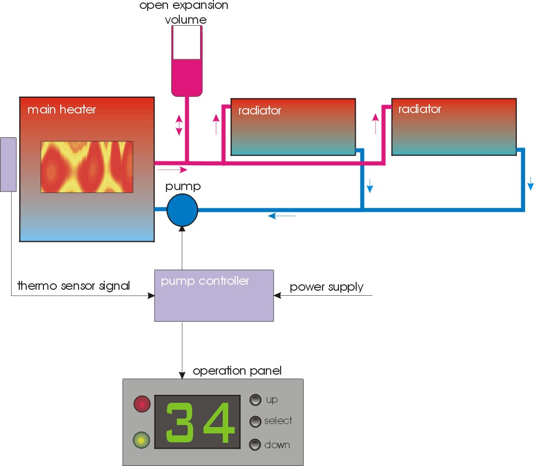
Main
block diagram:
(click
on picture to view it enlarged)
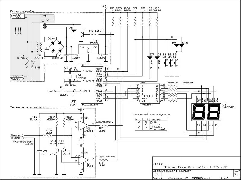
Schematic:
CAUTION: The
grayed area is HIGH VOLTAGE AREA. The voltage inside is AC 220
V and is very DANGEROUS for your life. If you are not experienced
electrician, it will be better for you NOT to mess with these things.
I can take NO RESPONSIBILITY for your health or even life if you
have not needed background to work with high voltage!
(click
on schematic to view it enlarged)
Used parts:
U1:
PIC16F84 (or PIC16C84 - no difference) - the heart of the system.
U2: 74LS74
- TTL BCD decoder used to drive LED indicator.
U3: VQE24E
- LED indicator (2 digits), common anode.
A1: 7805 - Voltage regulator, output:
5 Volts used to supply whole controller.
A2,A3:
Analog comparators used to realize themperature window.
D1..D4:
Power supply diodes (100 V/1 A).
TR1:
Power sullpy transformer (in:220 V, out:12 V, 300 mA)
D5,D9,D10:
Generic Si impulse diodes.
D7,D8:
LED's - the first red, the second green.
P1: Relay
(operating voltage:12 V) - used for switching the pump on/off. Caution:
controlled circuit has high voltage (~220 V)!
T1: Si npn transistor, (30 V, 250
mA, 500 mW).
Q1: Quartz crystal 4 MHz. Some types
of crystals have integrated capacitors. If such type is used, then C4
and C5 are not needed.
B1..B3:
Momentary action buttons, used for controller mode switching.
R18,R20:
Potentiometers for service adjusting themperature boundaries.
F1: Fuse,
burn-out current 0.5 Amperes.
SW1:
Mains switch.
All resistors
are 0.125 W.
All electrolythic capacitors
are at operating voltage 25 V or more.
Terminals 'Load'
are connected directly to pump motor.
Terminals '~220 V'
are connected to mains.
Terminals 'Therm'
are connected to thermistor (thermoresistor), mounted on main heather
back.
It is NOT enough to build the cirquit shown above in order to use it. An necessary part is embedded program. I wrote it using Mpasm by Microchip and put here the produced hex (this is ready to use object code). By clicking on coloured text you can download whole project including hex code and schematics. Having hex code you could embed it into PIC controller using a simple PIC programmer. You can download the programmer and programmer software that I use from here. There are a lot of such programmers over Internet.
Construction:
Here are pictures of some elements
of my home heating system.
-
HEATER
Manufactured by PRITY OOD - Lyaskovetz, Bulgaria. Approx. size: 44x48x90 cm. Heating power equivalence: 8 kW.
I connected it to the system using flexible shielded pipes seen on the picture. This allows me to move the heater around its place for service needs without disconnecting it from the system.
- RADIATOR
Manufactured by ALUMINA OOD - Shumen, Bulgaria. Material: alluminium. Sizes: various. Connected to the system using standard 1/2" pipes and fittings.
- OPERATION PANEL
This is user-interface part of the controller.
Manufactured by me.
Approx. size:
Panel:7x4 cm.
Controller (including power supply transformer): 10x10x6 cm.
- EXPANSION VOLUME
I'm not sure that this is the name but the meaning is: an open metal tank wich is used to compensate water expansion during themperature increasing. Normally its volume is about 1/10 of all water volume. In my case this means 2 litres. It is connected to the system using standard 1/2" pipes and fittings.
Operating:
The
system is fully automated, so once the time intervals (work/pause) and
themperature boundaries are set, you don't need to monitor it.
Themperature interval is set using R18 and R20 potentiometers. Low temperature
(for example 30 Celsius degrees) is the themperature at which controller
goes in stand-by state and waits until themperature goes over this point.
This mode is entered when the main heater is off. High themperature (for
example 80 Celsius degrees) is that one which tells the controller that
water is near boiling point. As boiling is not desired, when temperature
goes over this point, the controller switches the pump on and keep this
state until the themperature returns in normal window.
When temperature is normal (between Low themp. and High themp.) controller
switches the pump on and off according previously set time intervals.
Actually,
the controller supports four modes: Automatic mode, Programming Time On
mode, Programming Time Off mode and Manual mode. They can be switched
using the middle button (called 'Select') on operation panel. Before explaining
controller modes, I have to make some considerations:
Ton
- time interval in which the pump is on.
Toff -
time interval in which the pump is off.
Thyst -
time hysteresis (described below).
Tmax - maximal allowed themperature,
considered to be lower than water boiling themperature.
Tmin - minimal allowed water themperature,
considered to be equal to desired minimal environmental themperature.
- Automatic mode
(default) .
Controller enters this mode every time when the power is on. Once in this mode, controller switches on- and off- the water pump accordingly Ton, Toff, Tmin and Tmax settings.
When themperature is in normal boundaries (between Tmin and Tmax),controller counts down time intervals and switches the pump on/off. During this process the display is showing displaying the remining time (in minutes) for current state. When the pump is on, the green LED is on, when the pump is off, the red LED is on.
If, for some reason the themperature goes down Tmin, the controller stops the pump and waits until themperature returns into normal bounds. Until this is done, the controller is in stand-by state. This is indicated with red LED on and flashing display, showing Thist. When the themperature becomes normal, controller waits Thyst minutes and then starts the pump and time countdown.
If the themperature exceeds Tmax, then the controller switches the pump on and keeps this state until themperature becomes normal. This state is indicated with green LED on and flashing display showing Thyst. When themperature becomes normal, controller does not react immediately, but waits Thyst minutes, then stops the pump and starts time countdown.
Thyst (Ttime hysteresis)is a protective time interval, used to avoid multiple switching the pump on/off caused by themperature instability. Generally, it is set in software (firmware) to 1 minute and cannot be changed by user. When display flashes, pointing that themperature is not in normal bounds, it shows just the time histeresys.
Being in Automatic mode, the controller can be forced to switch pump on/off, ignoring remaining part of current time interval. This is done by pressing Up (pump on) or Down key (pump off). When this is done the controller starts to countdown proper time interval.
By pressing the middle button(Select), user can change controller mode to Programming Time On mode. - Programming Time
On mode.
This mode is used for setting Ton parameter. When controller is in this mode, the green LED is flashing and the display showing current Ton value (in minutes). Usind Up and Down button user can increase/decrease Ton value. The last set value for Ton is memorized in EEPROM (or Flash) memory, integrated in PIC and next time when the Automatic mode is entered, this value is used.
By pressing the middle button (Select), user can change controller mode to Programming Time Off mode. - Programming Time
Off mode.
This mode is used for setting Toff parameter. When controller is in this mode, the red LED is flashing and the display showing current Toff value (in minutes). Usind Up and Down button user can increase/decrease Toff value. The last set value for Toff is memorized in EEPROM (or Flash) memory, integrated in PIC and next time when the Automatic mode is entered, this value is used.
By pressing the middle button (Select), user can change controller mode to Manual mode. - Manual mode.
This mode gives the user ability to switch manually the pump on/off, ignoring all preset parameters. It is intended for service use. If you prefer to use this mode, it is cheaper to replace whole controller with standard switch :-).
By pressing buttons Up/Down user can switch on/off the pump. By pressing Select button, user can change controller mode to Automatic mode.
More:
Everybody
is free to use information about this project for his own needs. Information
shown here is enough for an intermediate technician to build a similar
system. I expect to receive some propositions for manufacturing the controller,
that's why I shall not publish here the program source code. The hex code
included in documentation is enough to build working system.
If you are interested by the system, but have some additional requirements
concerning controller capabilities and modes (for example to add more
thermo sensors, or make controller to display current water themperature)
and you are ready to pay for this, let
me know.
If you have some ideas about manufacturing this
and similar appliances, let
me know.
If you need additional information about the manufacturers mentioned above,
please e-mail me. I'll
send you more info about them.
This is not for the money, just my way to encourage Bulgarian industry.