Tutorial of IBM 750GX/GL Kit
------------------------------------------------------------------------------------------------------------------------------------------
The PowerPC 750GX/GL Evaluation
Board Kit hardware includes
·
The
evaluation board
·
Power
supply
·
Line
cord
·
Board
interface cables
1.
One
serial port cables for connecting the board’s serial ports to the host system
2.
An
Ethernet CAT6 cable is provided in the kit to support direct Ethernet
communication with the host system or a hub.
Features of the evaluation board
include
·
PPC750GX/GL
processor
·
Tsi108
system controller
·
512MB
DDR2 SDRAM Modules with ECC
·
512KB
8-bit socketed flash
·
32MB
32-bit FLASH
·
512KB
SRAM
·
32KB
non-volatile FRAM
·
Two
Gigabit Ethernet ports
·
Two
serial ports.
The PPC750GX/GL evaluation board
kit software includes
·
IBM
PowerPC Initialization Boot Software (PIBS) resident in the flash memory on the
board
·
PIBS
source code, the IBM Embedded PowerPC Operating System (EPOS)
·
Sample
application programs
·
Application
development libraries and tools
·
Compiler/linker/assembler
and associated binary utilities
·
IBM’s
RISCWatch, a source-level debugger that runs on the host system.
·
Technical
specifications
·
Board
schematics
---------------------------------------------------------------------------------------------------------------------
Contacting
the IBM Embedded Systems Solution Center
For information about
the PowerPC 750GX/GL Evaluation Board Kit and the IBM family of hardware and
software products for embedded system developers, check out the IBM
Microelectronics web site at:
http://www.chips.ibm.com/products/powerpc
Please send any
comments or questions regarding this product to the following Internet address:
---------------------------------------------------------------------------------------------------------------------
Host System
Requirements
This section describes the
hardware and software requirements of the host system to which the evaluation
board is to be connected. Supported host systems include:
·
PC
running one of the following: Windows 98/NT/2000/ME/XP
--------------------------------------------------------------------------------------------------------------------
Cygwin, Cross-Compiler, Binary Utilities
·
Complier
and A PowerPC gcc cross compiler is needed to compile or add functionality to
the sample application code provided in this evaluation kit.
·
The
process for building a gcc cross compiler is described in Building a GNU
Toolset For Use In Embedded PowerPC Cross Development.
·
This
document can be found in the evaluation kit software doc directory and
also online at www.ibm.com/chipcs/techlib.
Note: The software and
makefiles in this kit has been configured and tested to work with version 3.4.2 of the gcc compiler.
--------------------------------------------------------------------------------------------------------------------
Connect the evaluation board to the PC
Serial
Port Connection
·
The
serial ports are the stacked, standard 9-pin D-shell connectors labeled J13.
·
Looking
into these connectors, serial port 0 is the upper connector (J6-upper) and
serial port 1 is the lower connector (J6-lower).
·
Connect
serial port 0 (J6-upper) to the PC serial port using the supplied Null Modem
serial cable.
Ethernet
Port Connection
·
The
Ethernet ports are the two RJ-45 connectors with the single housing that is
labeled U2.
·
Looking
into these connectors, Ethernet port A is the left connector (U2-Left) and Ethernet
port B is the right connector (U2-Right).
·
Connect
Ethernet port B (U2-Right) directly to the PC Ethernet port using the supplied
crossover Ethernet cable.
Power
Cord
·
Connect
the power cable from the wall socket to the power supply.
·
Plug
the power connector from the power supply into the matching connector at the
top of the evaluation board.
·
Turn
the power supply switch on.
·
You
may not notice any movement of the power supply fan until the board is also
turned on.
--------------------------------------------------------------------------------------------------------------------
Power-Up and Resetting the Board
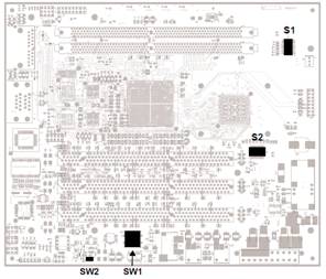
·
Power
on the evaluation board by pressing the button labeled SW1 on the evaluation
board.
·
Note
that the button labeled SW2 is the reset switch.
--------------------------------------------------------------------------------------------------------------------
Software for Serial Port Monitoring
From
the SourceForge website download the Realterm software for data reception and transmission
on the serial port
http://realterm.sourceforge.net/
Setting
·
In
“Display” tab
o
Check
“Scrollback”
·
In
“Port” tab
o
Baud:115200,
Parity: none, Data Bits:8, Stop Bits: 1, Hardware Flow Control: None
o
Select
“Port” number
o
Click
Button “Open”
·
In
“Send” Tab
o
Under
“EOL” check “+LF” (to have <enter> after we input text)
o
Select
“Literal” (to make backlash(\) a string in ASCII)
·
Press
the SW2, the reset switch.
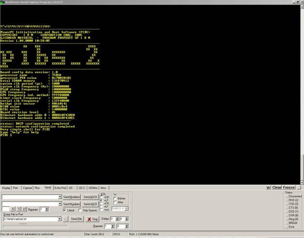
·
After
a few seconds you should see some board information scroll in the serial port
console window.
·
If
you don’t see the board information and the PIBS prompt in the serial console
window, check your connections and serial port configuration.
Configure PIBS
·
PIBS
is an initialization and boot program that allows you to interactively
configure the evaluation board by typing commands in the serial port console
window.
·
It has a help feature that describes commands
that can be used to configure the board.
·
The
commands are documented in detail in the PPC750GX/GL Evaluation Board Kit
User's Manual.
·
Configure the
Ethernet port
o
Configure
the Ethernet port with an IP address by setting the PIBS ifconfigcmd0 variable.
o
This
variable is used to configure an Ethernet port when the board is reset.
o
In
this example we specify network 0 (ent0) since we are using port B.
§
PIBS
$ set ifconfigcmd0=ent0 up 192.168.0.2 <ENTER>
o
Press
the reset button and the evaluation board will reboot and automatically
configure the Ethernet port.
o
Once
the board has rebooted, review the port configuration with the ifconfig command:
§
PIBS
$ ifconfig ent0 <ENTER>
§
ent0:
flags=63<UP,BROADCAST,NOTRAILERS,RUNNING> metric 0 inet 192.168.0.2
netmask ffffff00 broadcast 192.168.0.255
§
PIBS
$
o
Note
that a subnet mask of 255.255.255.0 (0xFFFFFF00) was implied in the initial
ifconfig command.
o
Your
output may vary slightly depending on prior configuration.
--------------------------------------------------------------------------------------------------------------------
Performing the
PING Test
·
You
should be able to “ping” your host now from the PIBS shell:
PIBS $ ping 192.168.0.1 <ENTER>
ping 192.168.0.1: 56 data bytes
64 bytes from 192.168.0.1: icmp_seq=0.
time=0. ms
64 bytes from 192.168.0.1: icmp_seq=1.
time=0. ms
64 bytes from 192.168.0.1: icmp_seq=2.
time=0. ms
----192.168.0.1 PING Statistics----
3 packets transmitted, 3 packets
received, 0% packet loss
round-trip (ms) min/avg/max = 0/0/0
PIBS $
o
Your
output may vary slightly depending on prior configuration.
--------------------------------------------------------------------------------------------------------------------
Configure the TFTP server
In order to use PIBS for
downloading applications via Ethernet, the host workstation must be configured
to support a TFTP server. A TFTP server
is included in the evaluation kit binaries available on CD.
·
Edit
the D:\IBM\ppc750gxgl-kit\bin\tftpaccess.ctl file.
·
Make
sure that it contains a line to allow access to the directory where you want to
compile your application.
·
In
this case we will use the sample directory, so the line in tftpaccess.ctl will
look like:
allow:d:\ibm\ppc750gxgl-kit\bsp_750gxgl\sample
·
The
TFTP server must be started on the host so that binary images that are built on
the host can be transferred to the target. Start the server by clicking
Start->Programs->IBM PowerPC
750GX/GL Evaluation Kit-> Start TFTPD server
·
Make
sure to restart the server if the PC is rebooted.
·
For
more information on installing and running the TFTP server see the PPC750GX/GL
Evaluation Board Kit User's Manual.
--------------------------------------------------------------------------------------------------------------------
Compiling the sample code
Once a gcc compiler is available,
follow these steps to compile the sample application.
·
Edit
the file d:\IBM\ppc750gxgl-kit\kernel_7xx\make\make.opt
·
Ensure
the COMPILER_NAME variable in this file is set to the prefix name of the
PowerPC gcc cross compiler.
·
If
the process described in the Building a GNU Toolset For Use In Embedded
PowerPC Cross Development document was followed, the correct COMPILER_NAME
will be powerpc-ibm-eabi-.
·
Edit
the file d:\IBM\ppc750gxgl-kit\bsp_750gxgl\make\make.opt
·
Ensure
the COMPILER_NAME variable in this file is set to the prefix name of the
PowerPC gcc cross compiler.
·
If the process described in the Building a
GNU Toolset For Use In Embedded PowerPC Cross Development document was
followed, the correct COMPILER_NAME will be powerpc-ibm-eabi-.
·
Ensure
the windows PATH environment variable contains the gcc cross compiler
directory.
·
In
a command prompt window, change to the d:\IBM\ppc750gxgl-kit\bsp_750gxgl\sample
directory and compile the samples by typing:
cd
c:\IBM\ppc750gxgl-kit\bsp_750gxgl\sample <ENTER>
make all <ENTER>
·
Note:
The make utility is available in the same environment used to build the
GCC compiler.
·
This
procedure creates several application images. T
·
he
following steps use the finaloram sample application image.
--------------------------------------------------------------------------------------------------------------------
Loading the sample code
·
The
PIBS bootfilename and ipdstaddr0 environment variables are used
to select the application file to load and the IP address of the host to load
the file from using TFTP.
·
The
TFTP server should already be running on the host as described in a previous
step.
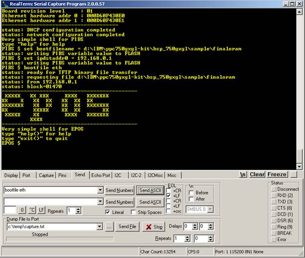
·
In
the serial port console window, set the PIBS bootfilename and TFTP host IP
address using the following commands:
PIBS $ set bootfilename = d:\IBM\ppc750gxgl-kit\bsp_750gxgl\sample\finaloram
<ENTER>
PIBS $ set ipdstaddr0 = 192.168.0.1 <ENTER>
·
You
can use the “set” command with no arguments to see a list of the variables and
their current values.
·
To
download and execute the finaloram image, execute the command:
PIBS $ bootfile eth <ENTER>
·
When
the download is complete, the finaloram program will begin to run and will
display the EPOS information banner and the EPOS shell prompt in the serial
port console.
·
To
execute the ping command from the EPOS shell type the command:
EPOS $ ping 192.168.0.1
·
Try
the “help” command for a brief description of the EPOS shell.
·
For
more information on EPOS see the PPC750GX/GL Evaluation Board Kit User's
Manual and the Embedded PowerPC Operating System User’s Manual which
are both located in the 750GX/GL Kit doc directory.
--------------------------------------------------------------------------------------------------------------------
Testing the Kit using EPOS (Embedded PowerPC OS)
Sample Code
Method-1(Inputting the code using the serial port
monitor)
·
When EPOS is running, user can
input command like a normal C language commands.
·
The functions/API supported by
the EPOS can be called and result will be displayed in serial monitor.
·
Read Embedded
PowerPC Operating System User’s Manual, for more details on the functions
and API’s.
Method-2(User modifies Sample.c file)
·
In
order to modify the sample EPOS program the sample.c file in BPS’s sample
directory can be edited.
·
User
application can be placed directly in sample.c file.
Method-3
(User creates own files)
·
Optionally
user application can be placed in a separate file and the makefile in
the sample directory can be edited in order to add the file containing
the user application to the sample EPOS program.
·
The
user application file name should be added to the OBJ list in the makefile.
·
After updating the sample.c file,
“gnumake ram” command can be used to rebuild the finaloram EPOS program.
·
The
compiler used to build the finaloram EPOS program must be the same as
the compiler used to build the EPOS libraries.