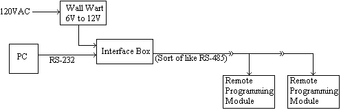
- Schematic: Network Overview
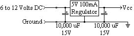
- Schematic: Power Supply
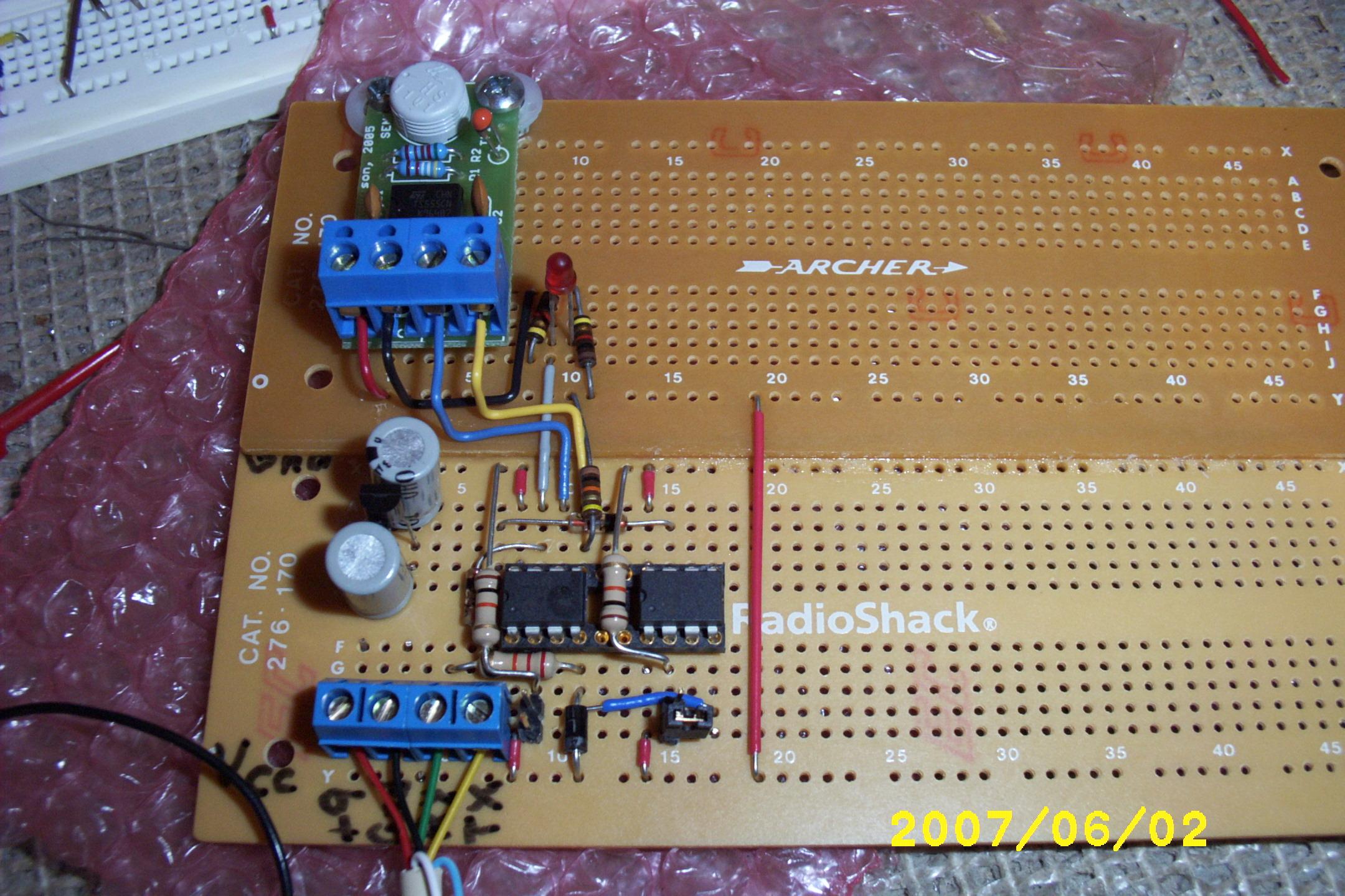
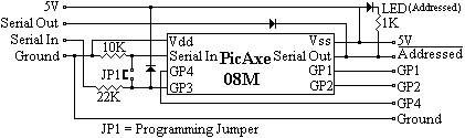
- Schematic: Remote Programming Module 08M
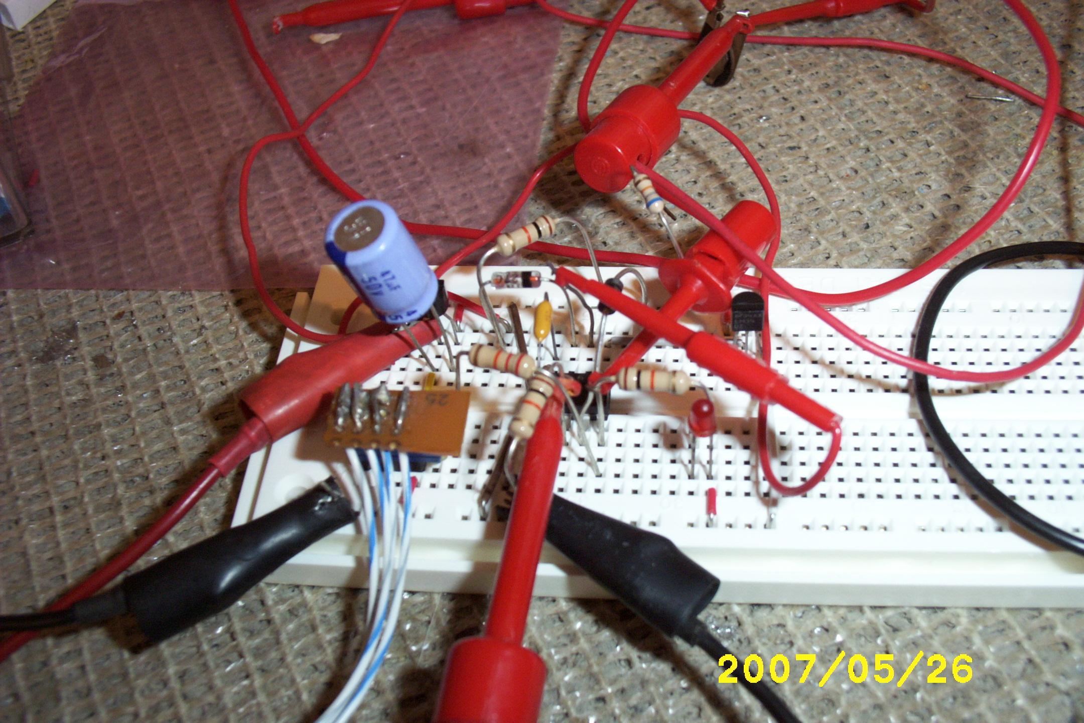
- Schematic: Sensors
 Lightning Strike!
This whole thing started with the idea of monitoring the moisture of the soil in my garden so I would know when to water it. (It's actually my girlfriend's garden, but it's in my backyard... don't ask.)
I figured I could measure the resistance between two probes and get an idea of the moisture content from that. So I set up a little "Test Unit" by filling a flower pot with moist soil and measured the resistance between two nickels (I chose nickel because it doesn't corrode easily) and got about 2K Ohms. Wondering if temperature would affect the measurement, I put the "Test Unit" in the refrigerator overnight and the measurement went up to about 3.5K Ohms (did the soil loose some moisture overnight?) Next I put it in direct sun light for several hours to heat it up and the measurement went down to about 1.5K Ohms. Sure enough, not only does temperature affect the reading by approximately 7.5% per Degree C, but it appears that moist soil (at least the sample I'm using) has a negative temperature coefficient! (Almost all known conductive materials have a positive temperature coefficient where the resistance goes up with temperature, moist soil, however, goes down making it somewhat of a rarity.)
So a few brain cells fired and I got the idea that I could put a little Microprocessor out there in my garden with a wire running in to the house and remotely monitor the soil. Then I figured that as long as I'm doing that, I may as well add other sensors too. Eventually (after even more brain cells fired) the idea blew out of control to become a Multi-Drop Network with an array of Addressable Microcontrollers each scanning an array of Sensors and reporting the data back to a master PC which will archive the data and graph it. What started as a single soil moisture measurement became an automated network measuring...
Table of Contents:
Lightning Strike!
The Multi-Drop Network is somewhat similar to RS-485 (but, definitely doesn't meet the specs for RS-485.) The protocol (to easily work with the PicAxe's abilities) I came up with is...
Protocol
"[aaaaa]f;data1;data2;data3;"
Where...
"[" and "]" are Required
"aaaaa" are the Unit's Address (MUST be 5 AlphaNumeric Characters long)
"f" is Function: 0 to 65535
"dataX" is Data Elements 1, 2, and 3 : ALL are Required 0 to 65535 (even if not used by the function)
";" is a separator character
Address [00000] is Reserved for Master.
Function/Data 0; 0; 0; 0 is Reserved, Returns Chip & Version (in this case "08mv10" for PicAxe 08M program Version 1.0).
Top
The Remote Programming Modules are just PicAxe 08M's with a custom program that give you the following abilities under software control of the Master PC...
| Output Function | Number | Data1 | Data2 | Data3 | Description | |
| Low | 000 | Pin | Makes Pin Low | |||
| High | 001 | Pin | Makes Pin High | |||
| PulseOut | 002 | Pin | Period | Puts a Pulse on Pin for Period | ||
| PWMOut | 003 | Pin | Period | Duty | Puts continuous PWM signal on Pin for Period / Duty Cycle | |
| Servo | 004 | Pin | Duty | Duration | Puts Servo signal on Pin for Duty Cycle | |
| Input Function | Number | Data1 | Data2 | Data3 | Description | |
| Pins, Outputs | 100 | Returns the value of Pins and Outputs | ||||
| ADC10 | 101 | Pin | Delay | Returns the ADC10 value on Pin after Delay | ||
| Count | 102 | Pin | Period | Delay | Returns the Pulse Count value on Pin for Period after Delay | |
| PulseIn | 103 | Pin | State | Delay | Returns the Pulse Width value on Pin starting from State after Delay | |
| DS18B20 | 104 | Pin | Delay | Returns the data returned from a DS18B20 on Pin after Delay | ||
The Remote Programming Modules return exactly the command they receive, plus "Value1;...". So if I send "[aaaaa]0;0;0;0;" over the wire to a Module with address "[aaaaa]", the Remote Programming Module will return "[aaaaa]0;0;0;0;08Mv10;" (exactly what it received plus the data "08Mv10;" - Chip & Version number.) I have grandiose plans of having these Remote Modules all over the house to Sense and Control stuff (automatic porch light, automatic sprinkler system, signal when mail has arrived, leak detectors under my sink, dishwasher and washing machine...)
Top
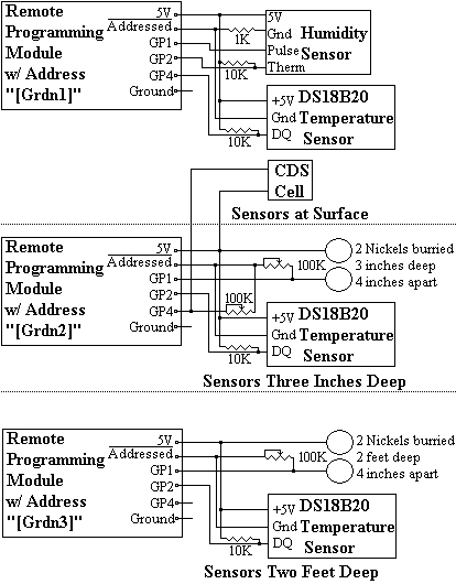
The buried sensors didn't need much protection (I covered all buried solder connections with epoxy to water proof them) but, the Remote Programming Modules have sensitive electronics and connections that could all be affected by weathering (in particular the Humidity Sensor would be destroyed if it actually got liquid water in it.) I made a protective housing from an outdoor electrical box held off the ground by electrical PVC tubing. I wanted to be able to see the "Addressed" LEDs lighting up with out removing the cover, so I cut a hole in the cover and epoxied clear plastic to it. The CDS Cell is mounted on top because it needs to point straight up to sense the Sun; and the surface temperature sensor is mounted underneath because it needs to be able to sense free air, but be shielded from the Sun.
TopThe code is pretty self-explanatory; GardenMon_PicAxe_08M.bas it...
Several of the sensors are tied to the *Addressed Pin (active low), so the input functions have the option of waiting for a short period of time for external sensors/electronics to stabilize.
TopThe Java code is written from the point of view of performing I/O on individual pins. There are several sections...
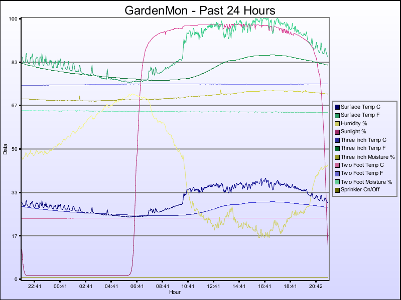
It really does work. Here is a sample debug output during development. It gets updated every minute, 24 hours a day...
	GardenMon Summary
		Time			: Mon Jul 09 20:44:28 EDT 2007
		Raw Humidity		: 44.69190000000003
		Humidity C		: 24.0657493210428
		Corrected Humidity %	: 44.65014656208114
		Surface Temp		: 30.9375 C, (87.6875 F)
		Surface Due Point	: 17.49014611339381
		Sun Intensity %		: 10.4644775390625
		3 Inch Temp		: 27.8125 C, (82.0625 F)
		3 Inch Moisture %	: 71.1578369140625
		2 Foot Temp		: 23.875 C, (74.975 F)
		2 Foot Moisture %	: 64.1265869140625
		Sprinkler is		: Off
waiting for Next Minute...
One day we had a good hard rain and I could see it the graph of the data; the surface temperature suddenly dropped, the light intensity dipped, the humidity rose, and the three inch moisture sensors indicated an increase. Later that day I was on the phone with my girlfriend and she said it had also rained early in the morning (I must have slept through it;) I looked at the data again and there it was... now that I knew what to look for I could see from the data that it started raining at about 05:10 in the morning. That's when it struck me that this thing really does work!
Top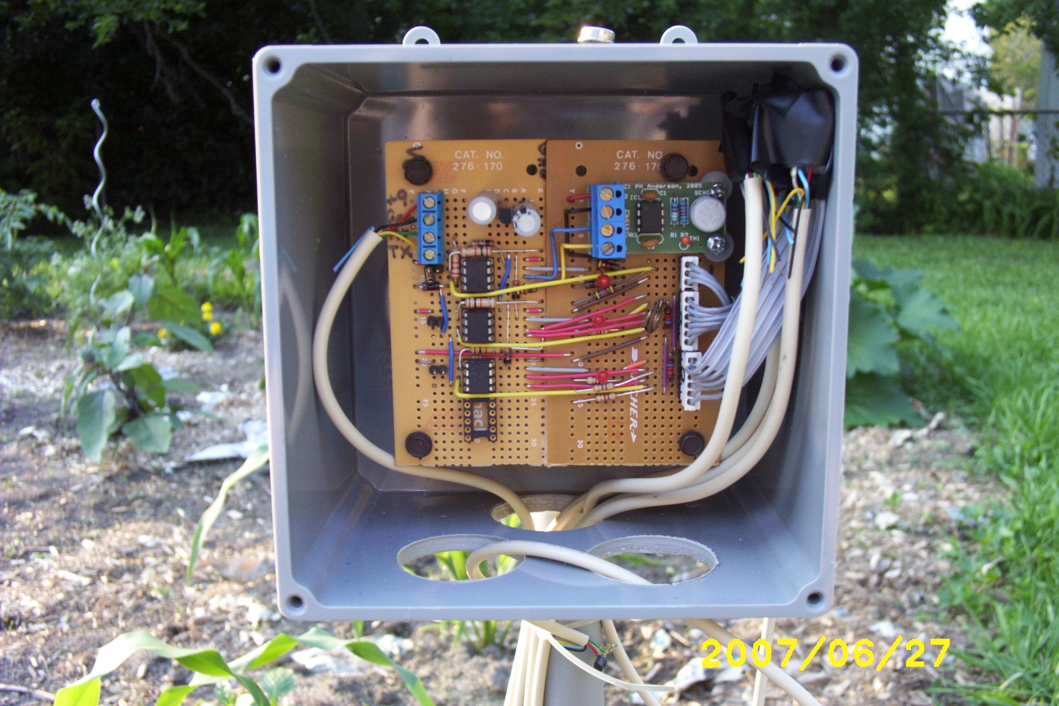
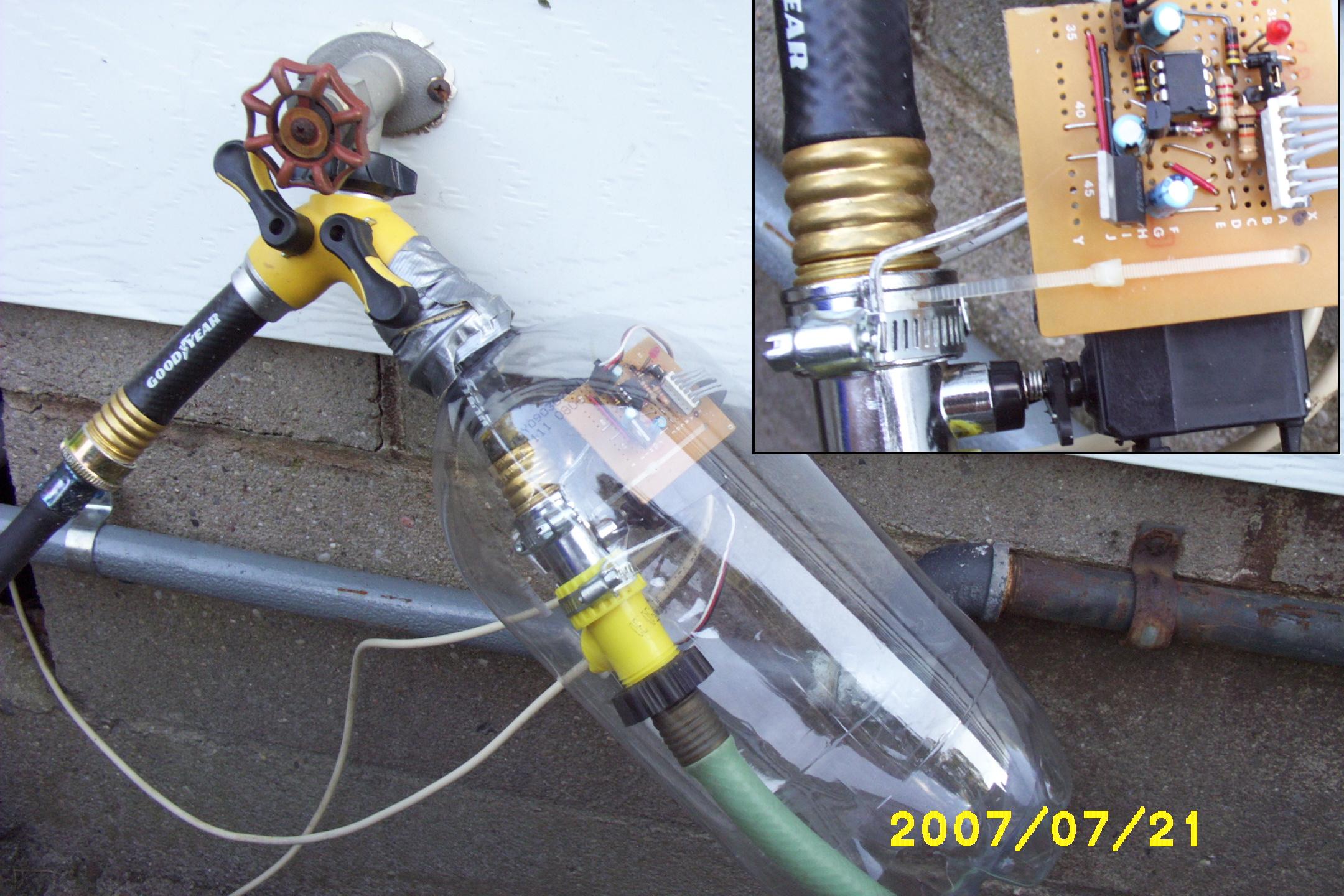
Originally I intended to only gather data with this project to help decide when and how long to manually water the garden, but once all that was working I realized that automatically controlling a sprinkler was a natural extension (besides, I was tired of getting up at the optimal time for the garden of 05:00 to turn the water on.) I bought a small valve at a hardware store and hooked up an RC Servo to open and close it. It would be much cooler if the program figured out when and how long to water the garden from the sensor inputs, but for now I just program on/off days/times (it is best to water a garden just before dawn so the Sun can dry off the leaves at day break.) Of course it would have been easier to buy a simple pre-built watering timer specifically made for the purpose, but then I wouldn't have the satisfaction of knowing I built it myself.
There are other graphs for Past & Last Hour, Yesterday, Past & Last Week, Past & Last Month, Past & Last Three Months, and Past & Last Year; however, space restrictions here on GeoCites won't let me make them available. (The "Past" graphs always end with the most recent reading, and the "Last" graphs always begin at the previous Hour, or 00:00 on the previous day, week(Sunday), month(1st), or year(January 1st).)
Top
Lightning Strike!
Came home from work one day, looked at the Graph like I always do when I first get home, and saw that all the sensor readings had flat-lined since about 11:00 in the morning. Then I got a lump in my throat as I remembered that at work we had a good thunder storm come through at about that time (or was that a bad thunder storm.) I later heard my next-door neighbor say it sounded like it hit right in their backyard.
Some quick measurements with a Multi-function Meter revealed that the Serial Port on my good laptop was blown out; the voltage swing was from about minus 8V to minus 15V (it should be from plus 15V to minus 15V.) Substituting my lower-grade laptop gave me good Serial Port voltages, but that wasn't the only problem because none of the Remote Programming Modules (PicAxe 08Ms) were working either; it seems that the lightning also knocked the program out of them. They couldn't have been too severely damaged, however, because I was able to re-program them; just the EEPROM's were erased.
I ordered a USB to Serial Converter off E-Bay for about $8 to replace the damaged Serial Port on my good laptop. In the mean time, while waiting for that to come in, I experimented with putting smaller and smaller values of resistors between the TX signal on the Serial Port and the +12V Power Supply; eventually I found a value that would pull that -8V to -15V voltage swing up to the +1V to +4V range. Since the PicAxes have a Schmitt Trigger on the Serial-In (GPIO3), they were happy with that (but I doubt that the -15V power supply in the laptop was happy about being so heavily loaded that it was forced to put out +1V!) It may be a temporary kludge, but hey... it works! The USB to Serial Converter from E-Bay eventually came in and I hooked that up, reconfigured the gardenMon program to use it, and everything works fine now.
I remembered from looking at electronic equipment to see what makes it tick, that I always seemed to see some little capacitor looking things near the connector on phone-line equipment. After a little research I learned that they are MOVs (Metal Oxide Varistors) and are there to protect the equipment from voltage spikes (I didn't know that, but you learn something new every day.) So I stripped some from an old Answering Machine and an old Modem and put them in the Interface Box between my computer and the wire running out to the outdoor GardenMon equipment. Additionally, I used phone wire with RJ-11 connectors and ran it through a power strip with a surge suppressor intended to protect Phone/Modem/FAX. Hopefully that will guard against the next lightning induced voltage spike.
TopMost everything went very smoothly on this project (some of my past projects have been absolute disasters with so much going wrong that I gave up in disgust.) I only had one mis-wire; which was simply "off-by-one", and was easily corrected by resoldering a single wire one hole over.
I learned (the hard way) about using MOVs (Metal Oxide Varistors) on long wire runs to protect the equipment from voltage spikes.
I was using DC to measure resistance and thought it would be a good idea to wait one second to let it stabilize before taking a reading. However, after additional research I found that you should either measure with an AC signal, or measure with-in milliseconds (if using DC) to avoid gas from building up around the probes from electrolysis.
The basic principle of measuring soil moisture content was spot on, however. I had buried the sensors and then poured mud made from the very same soil I had just dug up down the hole; exactly what I later read that professional installers do! I will stick with these sensors for this season, but next year I will make and calibrate "Gypsum Blocks", which is the technical name for the same thing packaged in a porous Plaster of Paris to make it more stable.
Top