 BACK TO MAINPAGE!
You are the
visitor to this page!
Item No. 31.
[was] CONFIDENTIAL
Reported by R. Hurst, M. of S.
B.I.O.S.Trip No. 2394
BIOS Target Number: C31/4799.
BRITISH INTELLIGENCE OBJECTIVES SUB-COMMITTEE,
32, Bryanstone Square, London, W.1.
TABLE OF CONTENTS
										     Page No.

		I.  	Object of Visit and Summary ...........................		1

		II.    	Historical Notes

				1.   	The "Magnetstromapparat"......		        1

				2. 	The "Stromerzeuger"..................		2

		III.	Report

				1.	Interrogation of H.Coler.............	        3

				2.	Interrogation of F.Modersohn..		        4

				3.	Construction and Testing of
					the "Magnetstromapparat"........		5

		IV.	Conclusion.............................................		6

		APPENDICES

		Appendix I	Details of Stromerzeuger.........................	7

			      II	Report  by Professor Kloss....................	9

			     III	Report by Professor Schumann.............	15

			     IV	Report by Dr. Frohlich and Coler
				to O.K.M............................................	20


			       V	Report by Coler on Frohlich�s
				Experiment.............................................	29

		Figures 1 - 4
Coler is the inventor of two devices by which it is alleged electrical energy may be derived without a chemical or mechanical source of power. Since an official interest was taken in his inventions by the German Admiralty it was felt that investigation was warranted, although normally it would be considered that such a claim could only be fraudulent.
Acccordingly Coler was visited and interrogated. He proved to be co-operative and willing to disclose all details of his devices, and consented to build up and put into operation a small model of the so-called "Magnetstromapparat" using material supplied to him by us, and working only in our presence. With this device, consisting only of permanent magnets, copper coils, and condensers in a static arrangement he showed that he could obtain a tension of 450 millivolts for a period of some hours: and in a repetition of the experiment the next day 60 millivolts was recorded for a short period. The apparatus has ben brought back and is now being further investigated.
Coler also discussed another device called the "Stromer- zeuger", from which he claimed that with an input of few watts from a dry battery an output of 6 kilowatts could be obtained indefinitely. No example of this apparatus exists today, but Coler expressed his willingness to construct it, given the materials, the time required being about three weeks.
Opportunity was taken to interrogate Dr. F. Modersohn who had been associated with Coler for ten years and had provided financial backing. He corroborated Coler�s story in every detail.
Neither Coler nor Modersohn were able to give any theory to account for the working of these devices, using acceptable scientific notions.
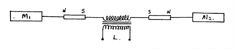
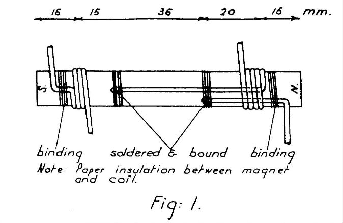
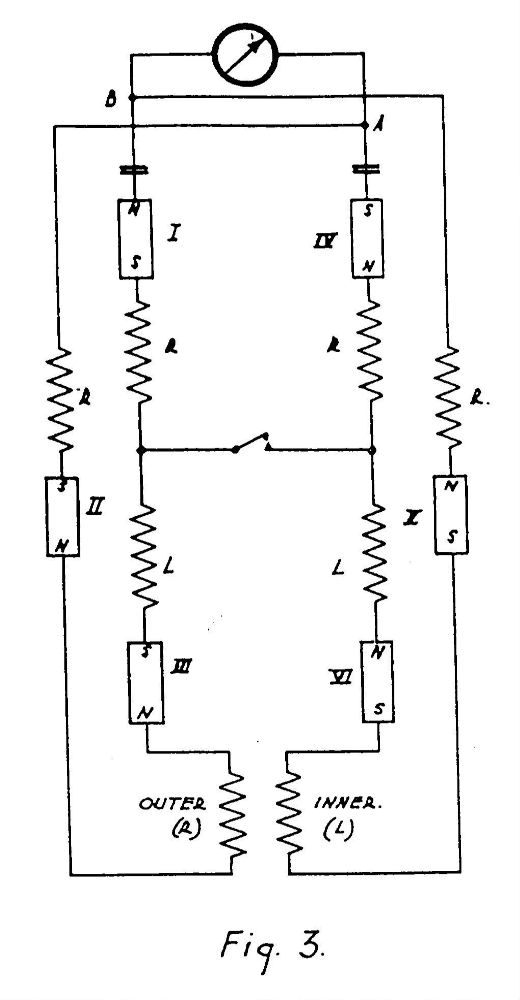
1. The "Magnetstromapparat"
This device consists of six permanent magnets wound
in a special way so that the circuit includes the
magnet itself as well as the winding,
(See Fig.1).
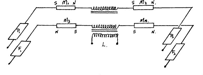
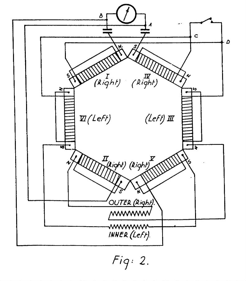
These six magnet-coils are arranged in a hexagon and
connected as shown in the diagram (Figs.
2 and 3),
in a circuit which includes two small condensers, a
switch, and a pair of solenoidal coils, one sliding
inside the other.
To bring the device into operation
the switch is left open, the magnets are moved
slightly apart, and the sliding coil set into various
positions, with a wait of several minutes between
adjustments.
The magnets are then separated still
further, and the coils moved again. This process is
repeated until at a critical separation of the magnets
an indication appears on the voltmeter.
The switch is now closed, and the procedure continued
more slowly. The tension then builds up gradually to
a maximum, and should then remain indefinitely.
The greatest tension obtained was stated to be 12 volts.
The "Magnetstromapparat" was developed by Coler
and von Unruh (now dead) early in 1933, and they were
later assisted by Franz Haid of Siemens-Schukert, who
built him self a model which worked in December 1933.
This was seen by Dr. Kurt Mie of Berlin Technische
Hochschule and Herr Fehr (Haber�s assistent at the
K.W.I.), who reported that the device apperently worked,
and that they could detect no fraud.
One model is said to have worked for 3 months locked
in a room in the Norwegian Legation in Berlin in 1933.
No further work appears to have been done on this system
since that date.
In 1925 Coler showed a small (10-watt) version to Prof. Kloss (Berlin), who asked the Government to give it a thorough investigation, but this was refused, as was also a patent, on the grounds that it was a "perpetual motion machine". This version was also
seen by Profs. Schumann (Munich), Bragstad (Trondheim)
and Knudsen (Copenhagen).
Reports by Kloss and Schumann are translated in
Appendics II and III.
In 1933 Coler and von Unruh made up a slightly
larger model with an output of 70 watts. This was
demonstrated to Dr. F. Modersohn, who obtained from
Schumann and Kloss confirmation of their tests in 1926.
Modershon then consented to back the invention, and
formed a company (Coler G.m.b.h.) to continue the
development.
At the same time a Norweigan group had
been giving financial support to Coler, and these two
groups clashed.
Modersohn�s connection with Rhein-
metall Borsig, and hence with the official Hermann
Goering combine gave him an advantage in this. Coler
then in 1937 built for the Company a lager version
with an output of six kilowatts.
In 1943 Modersohn brought the device to the
attention of the Research Department of the O.K.M.
The investigation was placed under direction of
Oberbaurat Seysen, who sent Dr. H. Frolich to work
with Coler from 1.4.43 to 25.9.43.
Frohlich was convinced of the reality of the
phenomena, and set about investigating the
fundamentals of the device.
He apperently concentrated on a study of the energy
changes which occur on the opening and closing of
inductive circuits.
At the end of the period he was
transferred to B.M.W. to work on aerodynamic problems
and is now working in Moscow.
In 1944 a contract was arranged by the O.K.M. with
Continental Metall A.G. for further development, but
this was never carried out owing to the state of the
country.
In 1945 the apparatus was destroyed by a
bomb, in Kolberg, whither Coler had evacuated. Since
that time Coler had been employed, sometimes as an
engineer and sometimes as alabourer.
Modersohn had severed his connection with Rheinmetall
Borsig, of which he had been director, and was working
for the russian authorities as a consultant in chemical
engineering.
Coler was questioned first about the history of his
inventions, when the details above were given.
He was then questioned about the theory of the
devices, but he was unable to give any coherent
suggestions as to the mechanism. He stated that
his researches (apparently conducted with crude
apparatus) into the nature of magnetism had lead him
to conclude that ferro-magnetism was an oscillating
phenomenon, of frequency about 180 kilohertz.
This oscillaation took place in the magnetic circuit
of the apparatus, and induced in the electrical circuit
oscillations the frequency which of course depended
on the values of the components used.
These two phenomena interacted, and gradually built up
the tension.
As the mechanism was not understood the proper
arrangement could not be worked out, but had
been arrived at by experiment, and the apparatus had
to be brought into adjustment by similar trial and
error methods.
Coler stated that the strength of the magnets did not
decrease during use of the apparatus;
and suggested that he was tapping a new sort of energy
hitherto unknow, -"Raumenergie" (Space-energy).
Coler gave a resume of the work done by Dr. Frohlich
for the O.K.M., and produced a copy of Frohlich�s
report, written jointly with himself (translation
reproduced as Appendix IV) and a report of his own
(part of which is given in Appendix V).
Coler was next asked if he would consent to
build models of these devices if material was made
available. He agreed that he could do this, and
stated that it would take one week to construct a
"Magnetstromapparat", and a month to construct a
"Stromerzeuger".
Accordingly we supplied the magnets, condensers and
copper wire needed for the former, and Coler
proceeded to build an apparatus as discussed in
Section 3. A list of material required for the
"Stromerzeuger" was drawn up by Coler.
room to another. All parts were visible and nothing
was hidden. As he was himself not expert he had tried
to get experts to examine it thoroughly, but reputable
scientists either refused to have anything to do with
it at all , or else were more concerned to find a fraud
than to see how it worked.
The exception was Dr. Frohlich, who was convinced of
the reality of the effect, and who also believed that
the secret was to be found in a analysis of the energy
changes in the special inductive circuit used.
He had made experiments to test his ideas, but
Modersohn denied knowledge of the results.
Modersohn was extremly methodical, and showed his
files on the subject: these contained copies
of all letters and reports concerning the device, since
1933.
On 1.7.46 experiments were being continued after
three days of fruitless adjusting, and when the magnets
were at a separation of about 7 mm. the first small
deflection was noted (about 9 a.m.).
The switch was closed and by slow adjustment of the
sliding coil, and by increasing the separation of the
magnets to just over 8 mm, by 11 a.m. the tension was raised to 250
millivolts and by 12.30 p.m. it was 450 millivolts.
This was maintained for another 3 hours when a soldered
tag became disconnected, and the meter slowely dropped
back to zero. Soldering up the broken connection did
not restore the tensinon. The magnets were closed up
and left overnight and the same procedure for finding
the adjustment was repeated on 2.7.46. After about
three hours a deflection of 60 millivolts was obtained; this was maintained for more then 30 minutes, but then decresed to zero when further adjustments were tried.
During all this work the model was completely open, and nothing could be hidden in it. The breadboard and meter could be picked up and moved round the room, tilted, or turned, without effect.
The apparatus would appear to be too crude to act as as a reciver of broadcast energy, or to operate by induction from the mains (the nearest cable being at least 6 feet away), and the result must for the moment be regarded as inexplicable.
Summary account of the "Stromerzeuger"
The basic element is that of an open secondery circuit, capacity loaded, inductively coupled to a primary circuit. The noval feature is that the capacities are connected to the secondary core through permanent magnets, as shown:-
The apparatus, in its construction already known to me from a previous inspection, consists of:
When asked why two batteries were used at all, Captian Coler
declared that for starting the apparatus a double battery is
necessary to get a second charge -impetus after exciting with the
one battery, and this for releasing the peculiar character of the
apparatus.
A test made towards the finish of a series of trails confirmed
this assertion in as much as the mechanism could not be
started with the single battery, on the contrary the "adjustment"
of the mechanism got disturbed.
Current-indicatores are built into each of the three circuits
mentioned, as well as volt-meters, behind some switch-resistances
necessary for the "adjustment".
Between the open ends of the two plate and spool-systems there
are therminal clamps for the effective circuit for whose loading
three bulbs of 8 volts are provided.
The apparatus was then put into action and above all the load
was tested with 2 lamps, 3 lamps and running light.
There-upon and by means of precision-instrument
(continuos current type)' Siemens & Halske Nr. 423820 the
indications of the built-in instruments were controlled by
switching on the mentioned precision-instrument in turn to the
single circuits, that is direct to the one terminal clamp
of the battery, in order to ascertian if perhaps through
any by-connections with the batteries, not conspicuous at
once, more current might be received than the built -in
instruments were showing.
The tests showed a sufficient conformity within the bounds of
measuring accuracy.
Finally the same instrument was switched on also to the effect circuit, whereby some greater differences with the instruments built into this circuit were shown; on the other hand, however, not such differences as to alter fundamentally the total result in any way.
In order to find out besides, whether the output current
might be identical with a wave-current overlapping
continuous current, the last control test was repeated
by using a hotwire-instrument furnished by me, make of
Hartmann & Braun, Nr. 254159.
In case there would have been such wave-currents, the hotwire-
instrument would have had to indicate a bigger current than was
shown by the continuous-current instrument.
In reality, however, a somewhat smaller current was found when employing
the hotwire-instrument. This may be explained by the fact
that the inner resistance of the instrument is about 10 times
greater than that of the continuous-current instrument, so that
when switching on the hotwire-instrument the load of the
apparatus was somewhat lessened.
The difference between 3.08 ampere measured with the
continuous-current instrument as compared with 2.95 ampere
measured with the hotwire-instrument is easily explained
when taking into account the divergences
of the two instrument-resistances.
Therefore one can infer from this test that in the
load-circuit we have to deal with real continuous current.
The results of the tests are compiled in the annexed table.
The figures show very well that the consumption of energy
in the exernal circuit is greater than the energy taken from
the batteries.
According to the curcuit, produced by Captain
Coler, which within this short time I could not check in all
its parts, the magnet-exciting circuit is fed by special
battery, completely separated from the other two circuits.
Consequently, a direct comparison of efficiency and consumption
of the apparatus would mean that only the sum of current of the
plate circuit and of the spool circuit would count.
After the established estimates with my own instrument and on a load of
three bulbs, there was resulting a current from the two mentioned
batteries of 0.215 + 0.070 = 0.285 ampere.
At the same time the three bulbs consumed ca. 3.7 ampere,
according to the built-in instruments, which is about 0.2 ampere
too much as was proved later on by a control of this instrument,
so that the real consumption has been about 3.5 ampere at a
tension of about 2.3 volt.
The reception of current from the two batteries in this case consequently was 1.7 watt while the consumption of the
BACK TO MAINPAGE!