
|
| ||||||
|
|
|
|
|
|||
|
|
|
|||||
If you can lay your hands on one of these, I recommend buying it on-the-spot with only one word of warning. The Estes 'E' motors that it was intended for have also been taken off the market due to high failure rates. I suspect the disappearance of their 'E' motors is the reason why Estes also discontinued The Shadow. A crying shame, this rocket is worth having. But on Estes D12-3's, The Shadow is a very poor performer that just clears 200'.
Of course, I decided to complicate matters and plan for both.
The answer to these goals was to utilize an interchangeable motor mount system. Nothing seemed to be available commercially, so I got creative. The most obvious solution was to use a BT coupler as the basis for a removeable 'cartridge' in the base of the rocket.
I had several pointers filed away about what to, and not to do wrt mounting techniques for fins and motor tubes. Using the coupler as a removeable MMT meant I couldn't very well mount the fins through the wall (TTW) unless I wanted to spend hours filing excess epoxy from the interior wall. Several people had also warned that centering rings were necessary at the leading edge of the fins on any rockets without through-to-motor-mount (TTMT) fin mounting. So the coupler would need to be long enough so that its forward bulkhead would be very near the leading edge of The Shadow's main fins. Happily, LOC's 2.6" tube couplers are exactly the right length for this.
Forward movement would be limited by epoxying another slice of coupler ahead of the cartridge to act as a "thrust ring". To keep the cartridge from falling out the back or being blown out by ejection pressure, 3 small aluminum sheet metal screws would pass through CA-reinforced holes in the BT and anchor into small plywood blocks epoxied to the inside of the MMT cartridge.
 The first motor cartridge is completed and equipped with two 24mm motor
tubes as shown. The exterior of the MMT cartridge was coated with CA for
reinforcement and durability. The same was done to the interior of the motor
tubes. No thrust blocks were installed in the motor tubes, just in case I
decided to try motors longer than 70mm. I've since found out that's extremely
unlikely. The only 24mm motors now available longer than 70mm seem to be 'F'
size, and there's no way I'm firing up two F's in The Shadow! So I may go
back and retrofit the motor tubes with thrust blocks. It'll save having
to wrap the D12-5's with a masking tape collar.
The first motor cartridge is completed and equipped with two 24mm motor
tubes as shown. The exterior of the MMT cartridge was coated with CA for
reinforcement and durability. The same was done to the interior of the motor
tubes. No thrust blocks were installed in the motor tubes, just in case I
decided to try motors longer than 70mm. I've since found out that's extremely
unlikely. The only 24mm motors now available longer than 70mm seem to be 'F'
size, and there's no way I'm firing up two F's in The Shadow! So I may go
back and retrofit the motor tubes with thrust blocks. It'll save having
to wrap the D12-5's with a masking tape collar.
(The thrust blocks were retrofitted as of 5/26/97)
For aft motor retention, I borrowed the idea of the "Kaplow Klip'. I epoxied a 4-40 hex nut between the motor tubes on the top of the lower MMT bulkhead. To ensure that the nut never broke loose, I encased it with an epoxy-soaked strip of cloth. A 4-40 hex cap screw with an aluminum washer threads into the nut from below and holds the two motors in.
The weight of the motor cartridge had me worried, so I attempted to ensure that all other weight was shifted as far forward as possible.
Mistakes:
I should have applied the CA before I glued in the thrust ring, and I
should have put it right up to the funnel-collector. I also should have used
a 2" length of coupler for the thrust ring, to provide a continuous internal
structure right up to the top of the collector. What I should have
done is reflected in the diagram below.
(The longer thrust ring was retrofitted as of 5/21/97)
 Stuffer Tube and Collector
Because there would be at least two 24mm or just one much more powerful 29mm ejection charge, I decided to enlarge the diameter of the stock stuffer from 24mm to 41mm. This size was chosen because it was the diameter of the BT of the Estes Mean Machine. Yep, I bought one and cannibilized 18" of its BT for The Shadow's stuffer tube. There's even enough left to build a not-so-mean version of the Mean Machine. The bigger stuffer tube dictated enlarging all of The Shadow's centering ring cutouts.
I was concerned about the possibility that the ejection charges might char the sides of the collector funnel. I also read that epoxy can catch fire if exposed to extremely high temperatures, so I shied away from coating the funnel with a layer of epoxy. I did find some aluminum tape at a hardware store that I decided to try. It's fairly thick, but is maliable enough to contour itself to irregular surfaces quite well. I cut wedges of this tape and applied it to the funnel and first 3" of the stuffer tube.
Mistakes:
I always cut out a fin-positioning template from a pizza-box lid to hold the fins in radial alignment while the epoxy is drying. I just slide it onto the BT and tack it in position over the fin positioning lines with masking tape. That way I only have to worry about their axial (lengthwise) alignment. An idea I will try in the future is to use two of these cardboard alignment guides, carefully taped into position for axial alignment as well. That way the fins will be locked in precise alignment in both directions.
When epoxying the fins onto the BT, I first put a dab of epoxy on each rivet hole with the tip of a toothpick. Then I applied a bead of epoxy to the fin root and put it in place. This causes the epoxy at the hole to be forced through the rivet hole in the BT wall. Getting another pair of hands to help, I then put elastics around the BT and over each fin to hold them in place. I used 3 elastics, one for each fin and they weren't weren't tight but just applied pressure. I smoothed the epoxy that got pushed through to the inside of the rivet holes with a piece of waxpaper. After rechecking the fin alignment every which way, I set the whole affair aside to dry.
Once the main and dorsal fins were mounted, I applied epoxy fillets as described in the online finishing article from the Sport Rocketry magazine. Lay the rocket down with two fins up in a 'Y' shape. Then lay a bead of epoxy on the inside/upper edge of each fin root and let it flow and smooth itself out. Using masking tape to get perfectly straight edges on the fillets has also been suggested, but I didn't and got very nice results. Do be careful not to let the epoxy run down at either end of the fins. Once those two fillets are dry, rotate the rocket and do the next two.
Mistakes:
 Shock Cord
I added an extra idea of my own and tied a square knot in the main loop, leaving a smaller loop to act as a ring for attaching the SC elastic. I epoxied and wrapped the square knot in duct tape. When I put the SC mount in place, I put the knots on opposing sides and such that the knot in the loop came right at the top edge of the BT when pulled to one side or the other. When packing the SC, the SC mount loop folds back into the BT and lays in the bottom of the parachute compartment.
I fastened the 3/8" SC elastic to the small loop at the top of the SC mount with a heavy ball-bearing fishing swivel.
Mistakes:
 I mounted my baffle up under the parachute compartment, instead of mounting
it right above the motor. That got the weight to work for me,
shifting the CG forward. Having the topmost baffleplate under the parachute
would also keep the recovery system from shifting rearward in rockets without
a stuffer tube. At Bob Kaplow's suggestion, I constructed it inside my upper BT
coupler. That allowed me to assemble it as a unit before gluing it into the BT.
I mounted my baffle up under the parachute compartment, instead of mounting
it right above the motor. That got the weight to work for me,
shifting the CG forward. Having the topmost baffleplate under the parachute
would also keep the recovery system from shifting rearward in rockets without
a stuffer tube. At Bob Kaplow's suggestion, I constructed it inside my upper BT
coupler. That allowed me to assemble it as a unit before gluing it into the BT.
The idea is to make the ejection charges thread through a non-linear path that cools the gasses and stops the straight-line trajectory of the superhot carbon particles.
As shown in the diagram, I made it out of three bulkhead-type baffleplates spaced 18mm apart vertically. On each baffleplate I drew four circles of 18mm diameter and spaced far enough away from the center to allow 2mm between each. At this point, the circles drawn on the baffleplates made them look like movie reels. Now on each plate, I cut out only TWO opposing circles. Leave the other 2 opposing circles alone, they were drawn to establish correct spacing for later consideration.
Next I cut 18mm wide strips of 1/16th balsa stock to fit on edge across the inside of the BT. These acted as reinforcement and flow-deflectors between each baffleplate. They are mounted as shown in an 'X' across the center of the baffleplate, with the holes and circles centered in each "wedge" section. This is why 2mm between the circles was needed, to allow space for mounting these cross-members between them. Each outer end of these cross-members also has an 18mm half-circle cut away. These allow ventilation from each wedge-section, to its two neighboring sections.
You could notch the cross-members to interlock, but I just glued one straight across and then took a 1/16th slice out of the middle of the other and butt-glued those two halves to either side of the midpoint of the first.
I stacked and glued the baffleplates together right in the coupler. I put a bead of glue around the inside of the coupler at the right depth, put glue along the top of the cross-members, and put the next baffleplate on top so that the holes of each section line up with the uncut (spacing) circles of the section above. There must not be a straight airflow passage.
After three launches, the 4 sheets of wadding I put in for peace of mind had gotten a little gray from smoke. But they showed no heat damage whatsoever.
How it works:
The ejection charge ignites and blows the motor cap(s) off. The gasses vent
into the ejection chamber above the motor cartridge and are directed into the
stuffer tube by the funnel-collector. The gasses then travel up the stuffer
tube (cooling all the way) until they hit the bottom-most baffleplate. Then
they are divided as they pass through the two holes in the first baffleplate
and enter separate chambers. Next, the gasses are diverted toward the rim of
the BT by the 'V'-shaped area formed by the cross-members. At the rim, each
ejection gas stream divides again and passes through the two half-circle
openings into the adjacent pie-wedge chambers. These each have openings
through the second baffleplate. The same thing happens all over again when the
gasses hit the third baffleplate.
You've likely noticed that 18mm figures prominently in the design of the entire baffle. This is based on the dual ejection charges from two 24mm motors. The inside diameter of those motor casings is approximately 18mm. It seemed like a good idea to provide two airflow routes for the ejection charges that preserve that size throughout. No, it isn't based on sound airflow or fluid dynamic principles, but it appealed to my common sense. Hey, I'm not a rocket scientist, I just pretend to be one.
If the BT diameter hadn't allowed just two holes in each baffleplate, I would have gone with smaller holes that added up to the same cross-sectional area. I probably couldn't have gotten away with the 'X' cross-members, but I still would have tried something similar to make the airflow route as indirect as possible. In the case of multiple smaller holes, I think it would also be necessary to have holes slightly larger to account for the increased circumferential (sp?) contact area. This phenomenon is illustrated below in an example of one 18mm (inside diameter) ejection casing...
IE:		    Sum of Areas        Sum of
# of   Diameter     of Circle(s)        Circumference(s)
Holes  of Hole(s)   (PI*r*r)*#          PI*dia*#

One    18mm         255sq mm            57mm
Two    13mm         264sq mm (132*2)    82mm  (41*2)
Three  10.5mm       261sq mm (87*3)     99mm  (33*3)
Four   9mm          256sq mm (64*4)     112mm (28*4)
The area in contact with the moving air (at the rims of the holes) increases as the holes get smaller and more numerous. The friction against the airflow would be more than doubled for four 9mm holes instead of one 18mm. To counter-act this, it would be necessary to allow more air through by enlarging the holes to maintain airflow volume.
Repairs In Progress
Well, if at first you don't succeed...
The Shadow is recovering from its brush with destiny.
The rear BT damage between the thrust ring and funnel collector has been straightened and smoothed. I did this by inserting broom handles into the twin motor tubes and clamping them horizontally. Next I removed the retaining screws from the motor canister and turned the BT to roll the wrinkle to the top. Then I suspended some weight on the upper end of the BT by just sliding a full roll of duct tape over the baffle-coupler. A few days of that yielded little or no improvement, so next I tried wetting the wrinkle to get it to straighten. I didn't soak it, just a little soap (to lower surface tension) and water. That worked like magic and removed 90% of the wrinkle. After that, I removed the old thrust ring with rasp, file and sandpaper. Then I reinforced the interior of the BT with CA right up to the funnel collector and installed the new, longer thrust ring. Next I filled, sanded, filled, and sanded some more. After repainting, it's as good as new!
The crushed upper length of BT was cut off to within an inch of the upper BT baffle-coupler. A new section of BT was put on with epoxy and a 2" long piece of BT coupler. More filling, sanding and painting yielded a fully restored Shadow.
I installed a new LOC-style SC mount from 3/16" nylon without knots , and made absolutely sure that the ends were completely covered in epoxy.
I haven't weighed the end result yet to see how much weight I've added. Hopefully no more than an ounce or so.
June 4/97 -The Shadow is ready to fly! But now I'm gonna be out of town for two weeks and have to wait to test it. Aaggh!
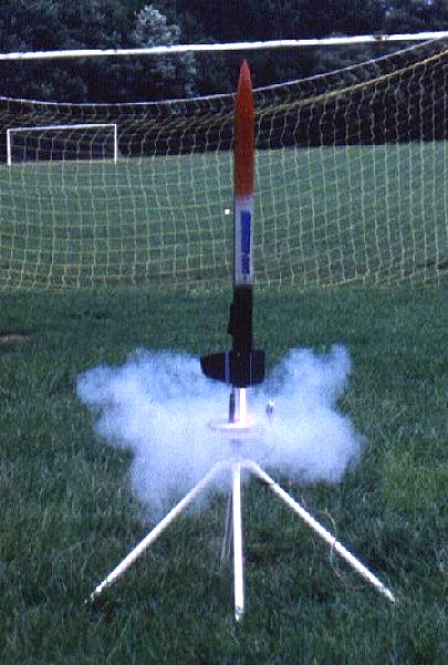
June 23/97 -The long separation from rocketry is over!