GC_ET_Phased-A.html
2021-01-15 14:51:49
2021-07-07 07:33:45

*** check back to GC_ET_AFX_CW_FiltRG.html
*** This is a discussion leading from page: "GC_ET_AFX_CW_FiltRG.html"
(1) from the rationale of the Functional Circuit
(2) towards a theoretical understanding of the Special Dual-Notch Generator Circuit.
*** This page is further analysis *** and incorporates data from that first page ***
*(: GC_ET_Circuit-Notch.html
***************************************************************************************************
*** Graphical Concept for the Dual-Notches
*** Where the wave-forms cross, there is zero difference in amplitude, F(1)-f(2)=f(notch) ,
*** and the Differential OPA produces the Dual-Notch effect !

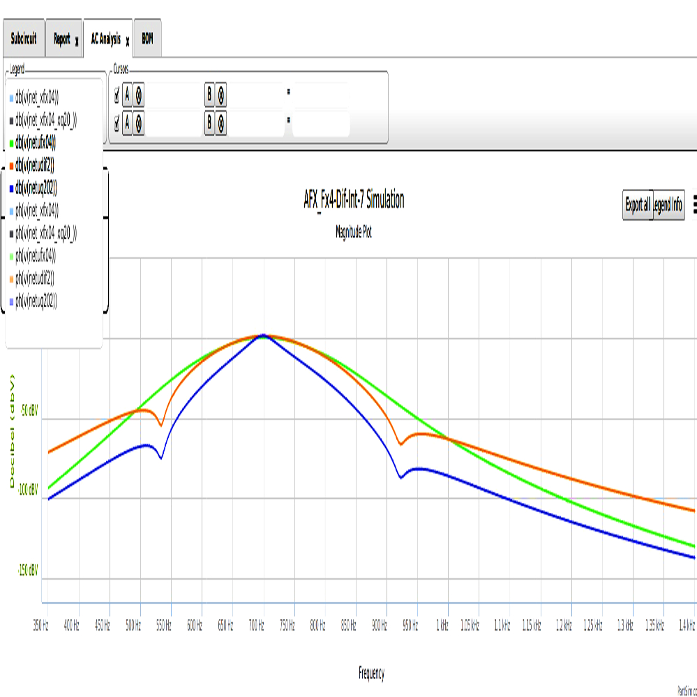
******* Dual Notches at -80 dB produce a Variance = 7 Hz sideband spread per dB attenuation
******* Results are Nearly Vertical Skirts down to -80 dB and lower.
*** IF the wave-forms cross, there is zero difference in amplitude,
F(1)-f(2)=f(notch)
*** THEN the Differential OpAmp can produce the Dual-Notch effect !
*** The depth of the Notches is determined by degree of phase-matching between the two signals !
*** The schematics show multiple MFB BandPass stages to synchronize the f(1) and f(2) signals.
************ example of Dual Notches at -80 dB.
************ BW@-3dB=70, BW@-80dB=350,
************ v=3.6 sideband spread per dB attenuation.

Goal : Brick-Wall Effect
ideally : Near "0" Hz sideband spread per dB attenuation.
( which would require infinite odd harmonic control )
Because perfect control of Odd Harmonics cannot be developed,
We explored techniques to produce Dual-Notches (above + below) f(0) .

Above :
(fig A) Ideal 100 Hz Brick Wall Fx ... the 'goal'
 from Elecraft data.
(fig B) DSP generated : Not an Analog waveform:
BW=100 Hz @ -3dB, BW=400 Hz @ -60 dB ...
DSP erases pass-band signals.

(fig C) AFX dual-notch filter: Analog Generated waveform:
BW=100 Hz @ -3dB , BW=350 Hz @ -60 dB.
AFX generates Dual-Notches to supress side-band signals.
******************************************************************************************************
Excellent Digital Model has been provided by
Dobromir Dobrev ... Ph.D ... Bulgarian Academy of Sciences
This is a Digital Signal Process Development by by Dr. Dobrev.
This digital documentation was developed using an entirely Digital Analysis of the AFX circuit concept.
It is remarkably close to the Analog Results that the author obtained.
At the -48dB level, the digital results are the same as the analog measurements.


Below:
Each Primary Plot shows the pulses of Signal Input .
1. Input signal is 532 Hz into the Filter f(0) of 700Hz .
2. Input signal is 700 Hz into the filter f(0) of 700 Hz.
3. Input signal is 923 Hz into the Filter f(0) of 700Hz .
Each secondary Plot shows the resulting signal output.
Plot #1 shows Signal Input 532 Hz ( Low Notch )
vs. Band-Pass of odd harmonics from attenuated signal.
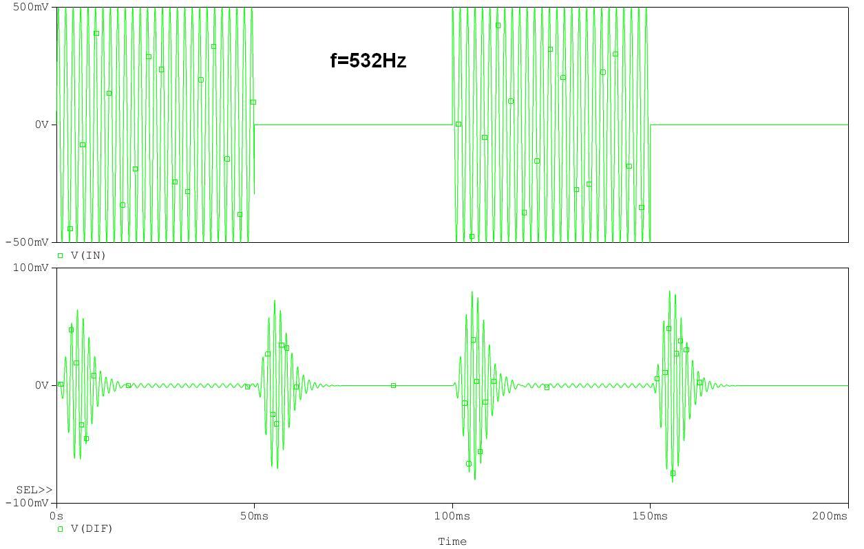
Plot #2 shows Signal Input 700 Hz
vs. tightly filtered PassBand Signal.

Plot #3 shows Signal Input 923 Hz ( High Notch )
vs. Band-Pass of odd harmonics from attenuated signal.

Summary :
Plot #1 shows Signal Input 532 Hz vs. Band-Pass of odd harmonics from attenuated signal.
Plot #2 shows Signal Input 700 Hz vs. tightly filtered PassBand Signal.
Plot #3 shows Signal Input 923 Hz vs. Band-Pass of odd harmonics from attenuated signal.
***************************************************************************************
( Leading to an Understanding of the Dual-Notches )
*
* Many designs were tried wherein different methods of generating and applying
Conventional Notches inverted into the Target PassBand.
*** List of project filters using conventional Notch Generation techniques.
*** These were also tested, and preseneted on this website:
Notched-Filter_7N
Notched-Filter_AAN
PC2D
P2S
P2D
* In General,
as the effectiveness of the Notch increased,
the tuning of the Notches became more critical.
*Therefore,
A different approach to generating Notches to attenuate sidebands was developed
based on Phase-Filtering and Non-Resonant concepts.
* This method is labeled the "Dual-Notch Phase-Filter Method"
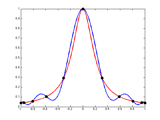
and we use a Runge Plot for description.
* By examining the (below) Runge Plot,
it can be seen that the Red and Blue waveforms cross each other
at +/- 0.2 from the central axis.
(1) If the Red and Blue waveforms are fed into a OpAmp in Differential mode,
then the difference between the two signals is seen as ZERO,
at the crossing point .
(2) The Zero Difference is transferred through the circuit as a Notch,
on both sides of the Central Signal.
(3) These Notches are produced by the differential of the original Waveforms,
(4) If the f(0) is changed up / down,
then the Dual Notches track according to the Phase-Crossings.
*

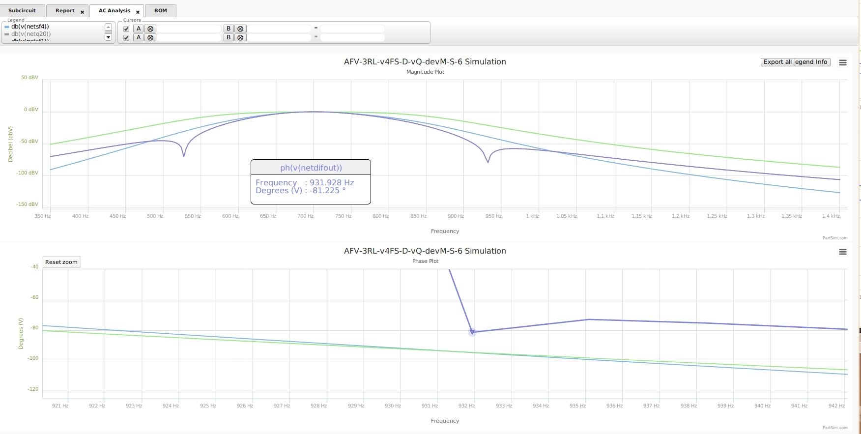
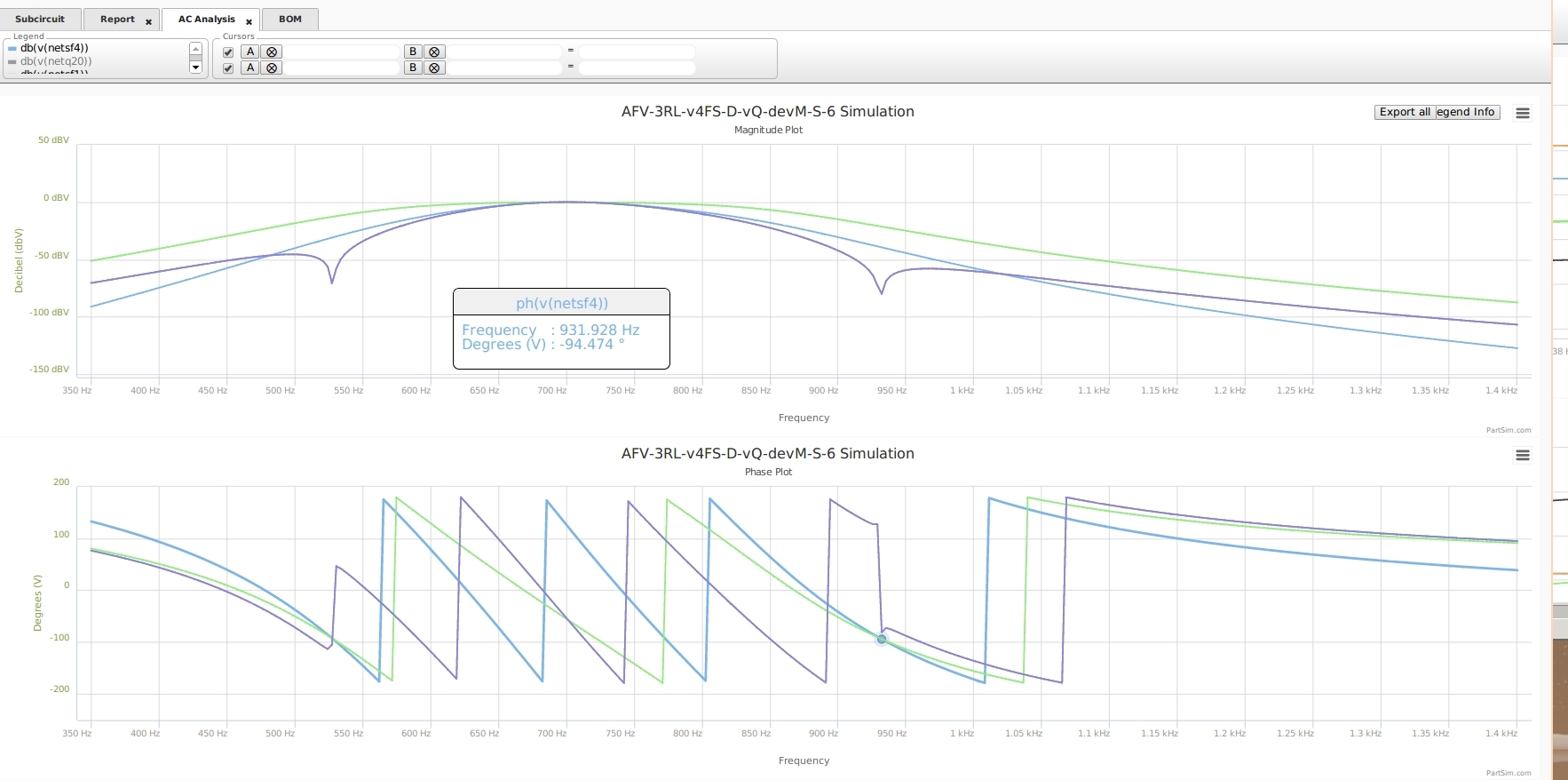
*** Below,
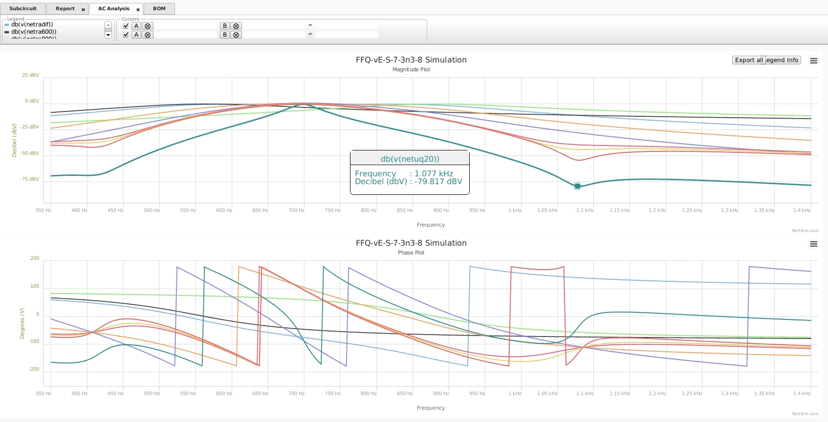
*** a full view of the Magnitude Plot,
*** showing that the Notch (upper) sits directly in phase with the Phase-Plot (below)

*** Below,
*** Zooming in close to the Phase-Crossing point ( Green and blue)
*** shows that the Notch occurs at that point.
*** Below,
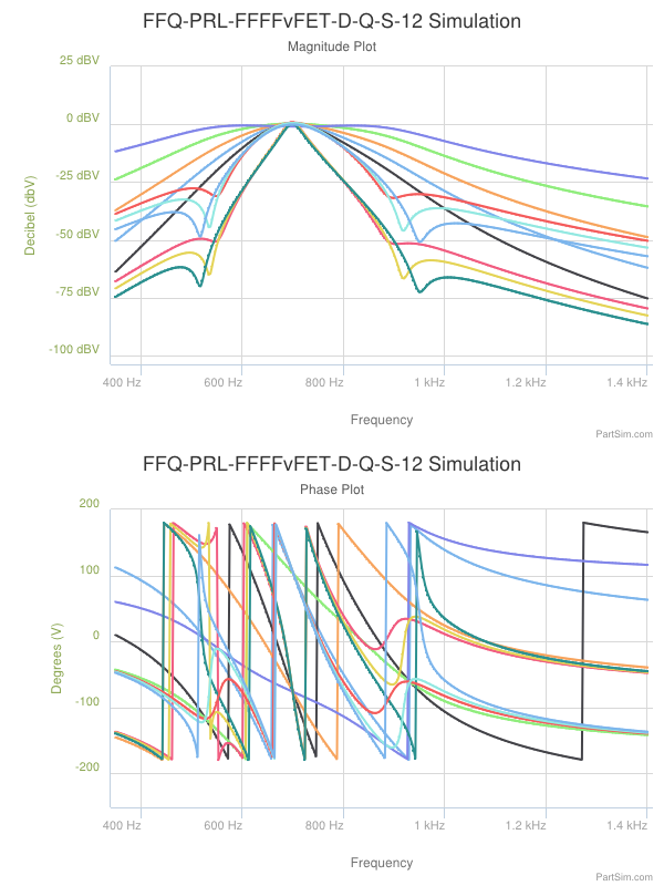
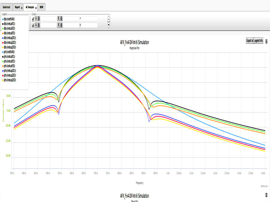
*** Firstly, a colorful display of the Fx04 waveform (blue) and the resulting Dual-Notches from an experiment.
*** Secondly, the lower Dual-Notches are the effect generated by a final Q=20 Narrow Filter,
*** ... which pushes everything down further -25 dB.
*** Commonly Selected PassBands :
Q=7 (BW = 100Hz)
Q=7N (BW = 100Hz + Dual-Notch)
Q=20N (BW = 35Hz + Dual-Notch )
*****************************************************************************
Below , just a collection of relevant jpg. More to be added as text is developed.
Below: Where the two phases cross... Below: Where the two phases cross...

Below : Dual Notches generated on both sides of the primary signal.


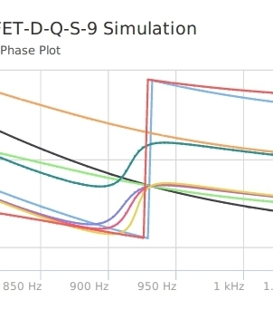
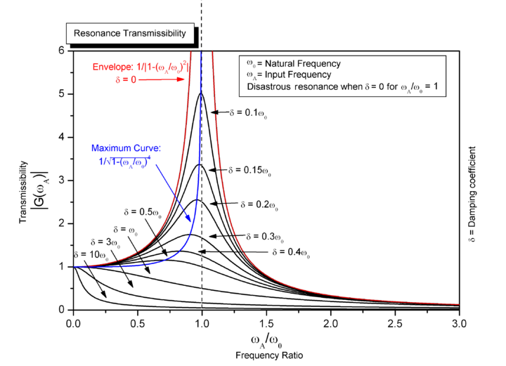
*** Raising the "Q" of the Filtering circuits increases the phase-shifting and increases distortion.
*** Raising the "Q" of the Notches inserted into PassBands increases the phase-shifting and increases distortion.
*** All meshing frequencies are affected and intermodulation distortion occurs.
*** source unknown for plot.
******************************************************************************************************************************************************


 from Elecraft data.


