GC_ET_AP_Ckt_A.html
2021-01-13 21:55:31
### 1RL-1Lo-12Hi design
### The "A" Developed working All-Pass circuit

 ... All-Pass HiPass circuit
First, some Electrical Theory from common Electrical Enginering textbooks :
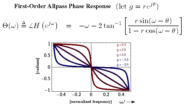
"The AllPass filter has frequency responses which must be zero at w=0 and at w=pi."
In all researched texts, the traditional academic texts specify
that AllPass filters CanNot be used for Low-Pass or High-Pass functions ,
nor for Band-Pass functions.
*** However, the author has developed working Dual-Notch Band-Pass circuits
*** which utilize the AllPass Filter in both LoPass and HiPass configurations
*** to perform the BandPass function,
*** and to produce Dual-Notches around f(0) .
******************************************************************************************************
*** In this #1 fully developed working circuit,
*** the authors accidentally tuned
*** all the All-Pass-filter stages to f(Lo) = 7 Hz and f(Hi) = 700 Hz ,
*** which accentuates the "w" notches at each "0" and each "pi" point in the spectrum.
*** Observing the useful Bode plots, we explored further, along this accidetal path.
*** In the #1 fully developed working circuit,
*** we preceeded and followed the All-Pass array
*** with Multi-FeedBack Band-Pass OpAmp filters
*** to reduce unwanted side-band signals ( away from f(0) = 700 Hz ).
*** The authors explored the "UnBalanced" ( 7 Hz and 700 Hz ) approach.
*** The All-Pass-Lo is tuned to 6.20 Hz (aprox. 7 Hz)
*** The All-Pass-Hi is tuned to 692 Hz. (aprox. 700 Hz)
*** These were chosen to utilize standard resistor values.
******************************************************************************************
*** Further development was done using the"UnBalanced" design
*** with f(0) at 70, 137, 175, 350, 650 Hz vs. 750 Hz to observe the patterns.
***
*** Further development was done using the"UnBalanced" design
*** with filter pairs of 2, 4, 6, 8, 10, 12, 14, 16, 18, 24 to observe the patterns.
***
*** Further development was done using the"UnBalanced" design
*** with (1) AP-Lo at 700 Hz and (12) AP-Hi at 700 Hz
*** with good results.
***
*** Our design witth (1) AP-Lo at 700 Hz and (12) AP-Hi at 700 Hz
*** is presented here.
*** All observations confirm the validity of this design.
*
*
*******************************************************************************************
*********************************************************************
******* #1 Developed working circuit ,
*** Using the "UnBalanced"
*** ONE f(Lo) = 700 Hz and Twelve f(Hi) = 700 Hz method.
*** ... derived from an experimental accident.
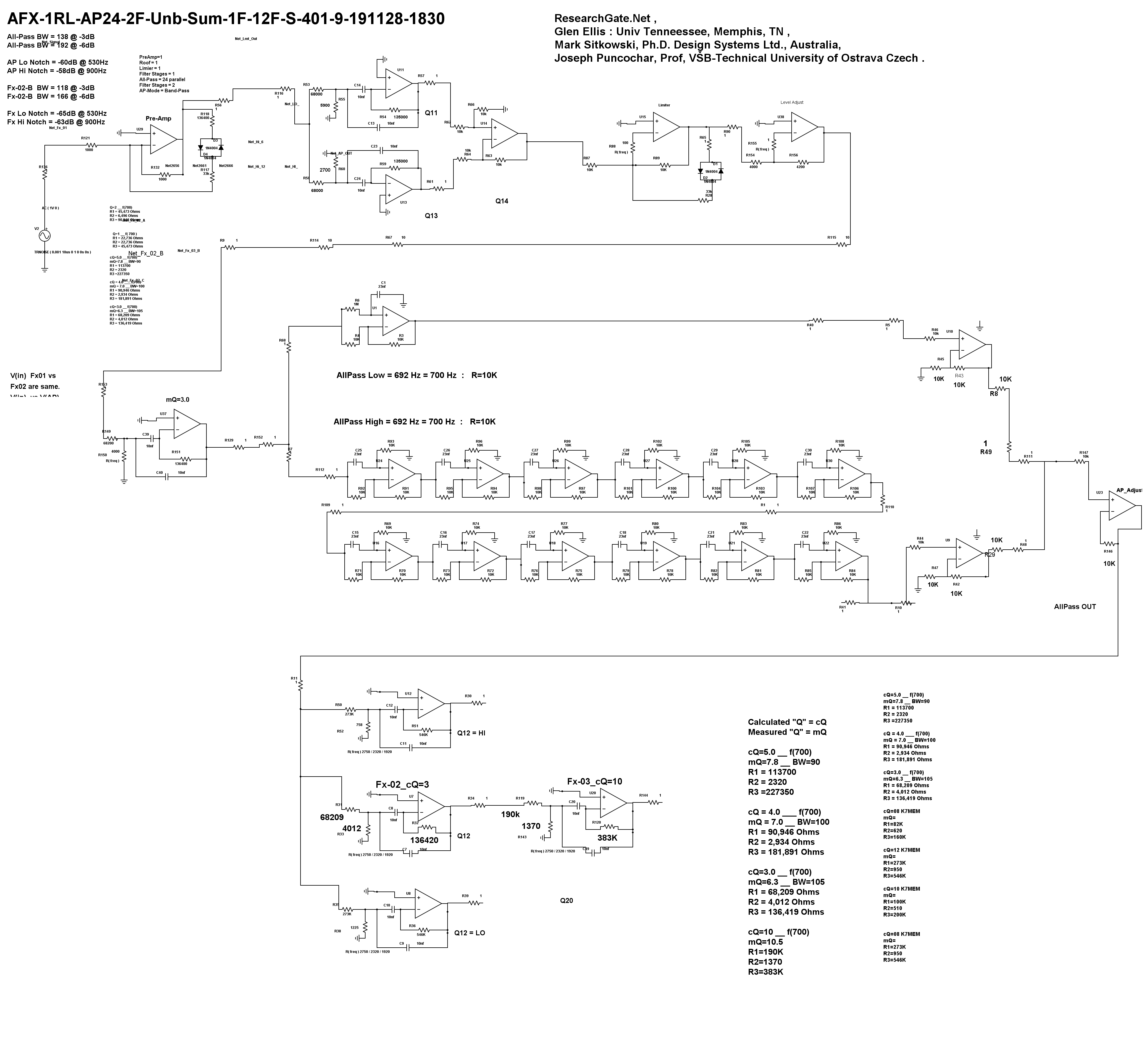
*** PreAmp, Roofing, Limiter,
*** Filter Fx01 Q=3,
*** 11 AllPass stages designed as
*** (1)LoPass
*** (12) HiPass All-Pass filters ,
*** f(0) LowPass = 700 Hz, f(0) HiPass = 700 Hz.
*** Combined Lo and Hi to produce
*** a Band-Pass Filter Signal.
*** Combined Lo and Hi to produce
*** a Dual-Notched Filter Signal.
*** Final Filters: Fx02 Q=5, and Fx03 Q=10.

.
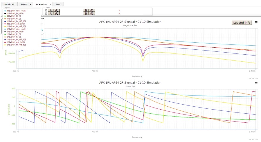
*** Below: Bode plot of Standard Circuit, AFX-1RL-AP24 .
*** Notice the Dual-Notches Yellow trace, around f(0)
*** Red trace is the final filter.
*** Notice the Sharp Fx-02 Q=3 final trace (Red) .
*** later versions used Fx-02 Q=3 and Fx-03 Q=10 for extremely sharp results. ( see down page )
### Below the All-Pass-Lo and the All-Pass-Hi is buffered and then is Summed in Filter-02
###
### 24 All-Pass : Bode Plot : Yellow trace is AllPass output.
###
### Plots LiteBlue, Red, DarkBlue show Filter-02 Q=3 when tuned +/- 70 Hz ( -3dB )
### within the All-Pass Output Yellow Trace.
### The Filter-03 ( Q=10 ) green-blue color is to be user selected
### and varied within the Filter-02 Band-Pass.
### The flat-topped trace is the "Roofing-Filter" which preceeds the Limiter circuit,
### provides a -27 dB per Octave attenuation of side-band signals, outside of BW=350Hz.
### The theory for the PreAmp, Roofing, and Limiter is explained in the "AFX" section.
*** This Version used Fx-02 Q=3 ( red ) and Fx-03 Q=10 ( narrow blue ) for extremely sharp results.
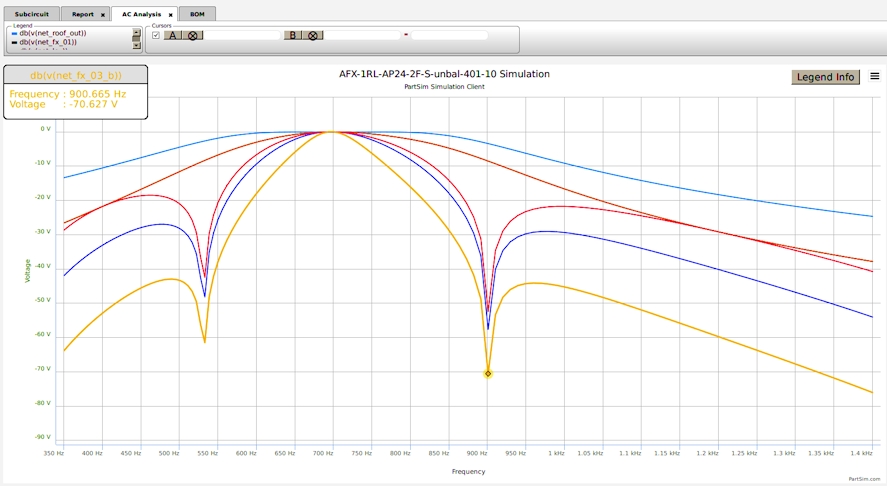
*** Scale : 700mV = -3dB ; 500mV = -6dB
*** Notch High 900 Hz = -53 dB, Notch BW = 360 Hz
*** Band Pass Spreads at the rate of 5.2 Hz per -dB attenuation ( aprox Brick-Wall ).

*** Below : Magnitude plot results with f(0) changed +\- to -3dB points.
*** f(0) Shifts are confined to the AllPass Ouput plot.
*** Magnitude Scale readings : V = -dB

*** Magnitude Scale readings : V = -dB
*** Red tick is APout at Hi-Notch = -52 dB
*** This APout Plot is a Non-Gaussian Shape.

*** Magnitude Scale readings : V = -dB
*** This Filter-03 Plot is a Gaussian Shape.
*** Yellow tick is Filter-03 at Hi-Notch = -70 dB

*********************************************************************

 ... All-Pass HiPass circuit

